
Service Manual User Manual
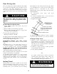
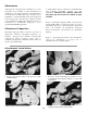
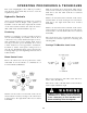

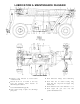
Table Of Contents
- 9020-7317 534B SERVICE MANUAL
- OPERATOR INSTRUCTIONS & LUBRICATION
- 8496 Operation & Lubrication Manual
- 8366 Operation & Lubrication Manual
- IMPORTANT SAFETY NOTICE
- INTRODUCTION
- SAFETY HIGHLIGHTS
- OPERATOR'S CAB
- CONTROL & INSTRUMENT IDENTIFICATION
- CHECKS & SERVICES BEFORE STARTING ENGINE
- ENGINE OPERATION
- WARM UP & OPERATIONAL CHECKS
- BRAKE SYSTEM
- STEERING SYSTEM
- DRIVE TRAIN
- MATERIAL HANDLING
- OPERATING PROCEDURES & TECHNIQUES
- PARKING
- STORAGE
- LUBRICATION & MAINTENANCE DIAGRAM
- 28327 Preventive Maintenance Chart
- HYDRAULIC SYSTEM
- 8497 System Operation Manual
- COVER
- NOMENCLATURE
- CAB CONTROLS AND GAGES
- ENGINE
- MAIN FRAME
- FRONT DRIVE AXLE
- DRIVE SHAFT
- REAR DRIVE AND STEERING AXLE
- TIRES
- TRANSMISSION & TORQUE CONVERTER
- STEERING CIRCUIT
- HYDRAULIC SERVICE BRAKE
- MECHANICAL PARKING BRAKE
- HYDRAULIC SYSTEM
- HYDRAULIC RESERVOIR
- HYDRAULIC PUMP
- MAIN CONTROL VALVE BANK
- MAIN PUMP CIRCUIT
- PILOT PUMP CIRCUIT
- HYDRAULIC CYLINDERS
- SWAY CIRCUIT
- LIFT CIRCUIT
- FRONT & REAR WHEEL DRIVE
- FORWARD / REVERSE LEVER (Neutral)
- FORWARD / REVERSE LEVER (Activated)
- INCHING
- TILT & COMPENSATING CIRCUITS
- OIL COOLER CIRCUIT
- CROWD (Boom In-Out) CIRCUIT
- AUXILIARY HYDRAULIC SYSTEM
- BOOM SECTIONS
- BOOM SLIDER PADS
- BOOM CROWD (IN-OUT) MOVEMENT
- MANUAL "QUICK-SWITCH" ASSEMBLY
- ELECTRICAL
- FUEL TANK
- 8369 System Operation Manual
- COVER
- NOMENCLATURE
- CAB CONTROLS AND GAGES
- ENGINE
- MAIN FRAME
- FRONT DRIVE AXLE
- DRIVE SHAFT
- REAR DRIVE AND STEERING AXLE
- TIRES
- TRANSMISSION & TORQUE CONVERTER
- STEERING CIRCUIT
- HYDRAULIC SERVICE BRAKES
- MECHANICAL PARKING BRAKE
- HYDRAULIC SYSTEM
- HYDRAULIC RESERVOIR
- HYDRAULIC PUMPS
- MAIN CONTROL VALVE BANK
- MAIN PUMP CIRCUITS
- PILOT PUMP CIRCUIT
- HYDRAULIC CYLINDERS
- SWAY CIRCUIT
- LIFT CIRCUIT
- FRONT & REAR WHEEL DRIVE
- FORWARD / REVERSE LEVER (Neutral)
- FORWARD / REVERSE LEVER (Activated)
- INCHING
- TILT & COMPENSATING CIRCUITS
- OIL COOLER CIRCUIT
- CROWD (Boom In-Out) CIRCUITS
- AUXILIARY HYDRAULIC SYSTEM
- BOOM SECTIONS
- BOOM SLIDER PADS
- BOOM CROWD (IN-OUT) MOVEMENT
- MANUAL "QUICK-SWITCH" ASSEMBLY
- ELECTRICAL
- FUEL TANK
- 81-515-009 Mico Sliding Caliper Disc Brakes Service Manual
- 81-600-001 Mico Guidelines for Installing Hydraulic Brake Components
- 81-950-016 Mico Brake Service Procedures
- 81-460-159 Mico Hydraulic Brake Valve
- 8497 System Operation Manual
- TESTING & ADJUSTING
- TROUBLE SHOOTING
- TRANSMISSION & TORQUE CONVERTER
- SM HR 182-3 Clark 18000 Series Powershift Transmission
- HOW THE UNITS OPERATE
- SECTIONAL VIEWS AND PARTS IDENTIFICATION
- DISASSEMBLY OF TRANSMISSION
- CLUTCH DISASSEMBLY
- CLEANING AND INSPECTION
- REASSEMBLY OF TRANSMISSION
- SERVICING MACHINE AFTER TRANSMISSION OVERHAUL
- TOWING OR PUSH STARTING
- SPECIFICATIONS AND SERVICE DATA
- LUBRICATION
- TROUBLESHOOTING GUIDE
- TYPICAL TWO AND THREE SPEED POWER FLOW
- PRESSURE CHECK POINTS
- CLUTCH AND GEAR ARRANGEMENT
- DRIVE PLATE INSTALLATION
- TRANSMISSION TO ENGINE INSTALLATION PROCEDURE
- SPEED SENSOR BUSHING INSTALLATION
- SM HR 182-3 Clark 18000 Series Powershift Transmission
- MISCELLANEOUS
- OPERATOR INSTRUCTIONS & LUBRICATION
This section highlights some common procedures
and discusses areas which may be new to even the
experienced operator.
Hydraulic Controls
All boom and attachment movements are governed
by hydraulic controls. Rapid, jerky operation of
hydraulic controls will cause rapid,jerky movement
of the load. Such movements can cause the load to
shift or fall or may cause the machine to tip over.
Feathering
Feather is a technique of control operation used for
smooth load handling. To feather controls, move
control lever very slowly until load begins to move,
then gradually move lever further until load is
moving at desired speed. Gradually move lever
toward neutral as load approaches destination.
Continue to reduce load speed to bring load to a
smooth stop. Feathering effect can be increased by
lowering engine speed at beginning and near end of
load movement.
Boom Control Lever
The boom control lever can be positioned to cause
individual boom movements or combinations of
boom movements as illustrated.
With boom raised above horizontal, forks can be
inserted under a load by moving boom control lever
forward and to the right until forks move forward
horizontally.
OPERATING PROCEDURES & TECHNIQUES
With boom raised above horizontal, forks can be
remove from a load by moving boom control level
back and to the left until forks move rearward
horizontally.
With boom lowered below horizontal, forks can be
inserted under a load by moving boom control lever
back and to the right until forks move forward
horizontally.
With boom lowered below horizontal, forks can be
removed from a load by moving boom control lever
forward and to the left until forks move rearward
horizontally.
The closer the boom to horizontal, the less boom
raise/lower movement required for inserting and
removing forks.
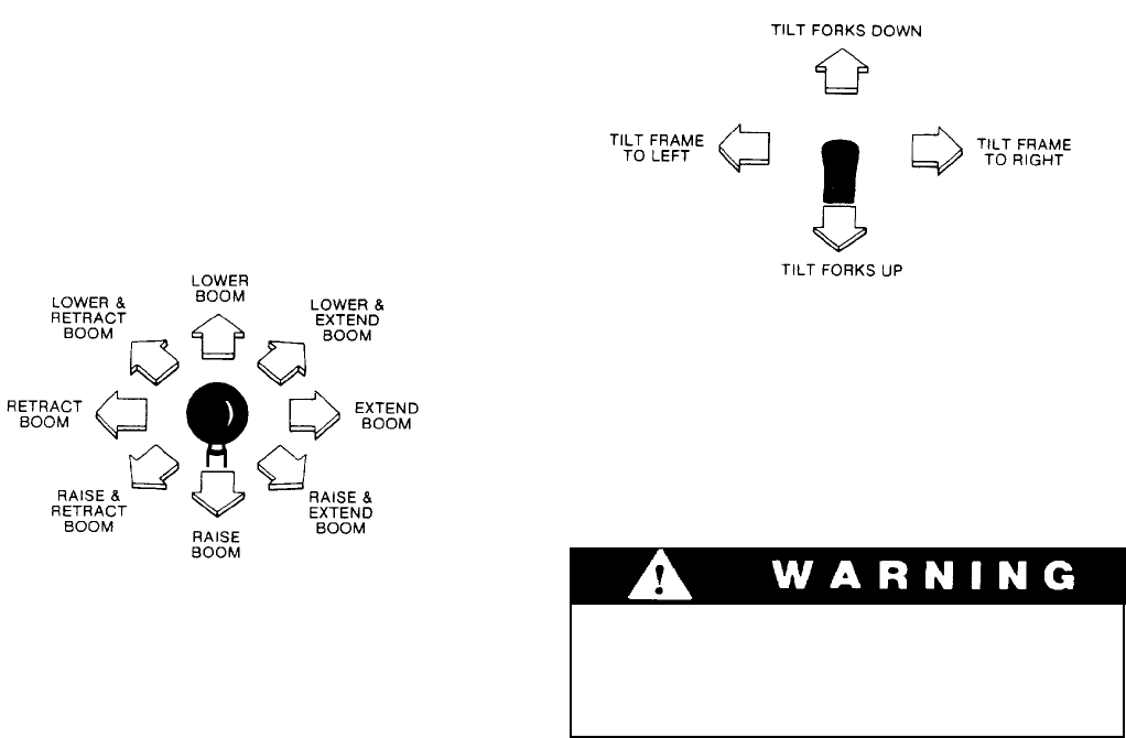
Carriage Tilt/Machine Level Lever
Move lever forward to tilt forks down and move
lever to rear to tilt forks up.
Move lever to left to tilt main frame to left and move
lever to right to tilt frame to right.
Always move boom to carry position
(horizontal or below) before leveling
frame. Attempting to level machine with
boom raised may cause it to tip over.
15