
Service Manual User Manual
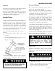
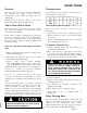
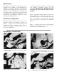
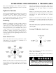

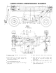
Table Of Contents
- 9020-7317 534B SERVICE MANUAL
- OPERATOR INSTRUCTIONS & LUBRICATION
- 8496 Operation & Lubrication Manual
- 8366 Operation & Lubrication Manual
- IMPORTANT SAFETY NOTICE
- INTRODUCTION
- SAFETY HIGHLIGHTS
- OPERATOR'S CAB
- CONTROL & INSTRUMENT IDENTIFICATION
- CHECKS & SERVICES BEFORE STARTING ENGINE
- ENGINE OPERATION
- WARM UP & OPERATIONAL CHECKS
- BRAKE SYSTEM
- STEERING SYSTEM
- DRIVE TRAIN
- MATERIAL HANDLING
- OPERATING PROCEDURES & TECHNIQUES
- PARKING
- STORAGE
- LUBRICATION & MAINTENANCE DIAGRAM
- 28327 Preventive Maintenance Chart
- HYDRAULIC SYSTEM
- 8497 System Operation Manual
- COVER
- NOMENCLATURE
- CAB CONTROLS AND GAGES
- ENGINE
- MAIN FRAME
- FRONT DRIVE AXLE
- DRIVE SHAFT
- REAR DRIVE AND STEERING AXLE
- TIRES
- TRANSMISSION & TORQUE CONVERTER
- STEERING CIRCUIT
- HYDRAULIC SERVICE BRAKE
- MECHANICAL PARKING BRAKE
- HYDRAULIC SYSTEM
- HYDRAULIC RESERVOIR
- HYDRAULIC PUMP
- MAIN CONTROL VALVE BANK
- MAIN PUMP CIRCUIT
- PILOT PUMP CIRCUIT
- HYDRAULIC CYLINDERS
- SWAY CIRCUIT
- LIFT CIRCUIT
- FRONT & REAR WHEEL DRIVE
- FORWARD / REVERSE LEVER (Neutral)
- FORWARD / REVERSE LEVER (Activated)
- INCHING
- TILT & COMPENSATING CIRCUITS
- OIL COOLER CIRCUIT
- CROWD (Boom In-Out) CIRCUIT
- AUXILIARY HYDRAULIC SYSTEM
- BOOM SECTIONS
- BOOM SLIDER PADS
- BOOM CROWD (IN-OUT) MOVEMENT
- MANUAL "QUICK-SWITCH" ASSEMBLY
- ELECTRICAL
- FUEL TANK
- 8369 System Operation Manual
- COVER
- NOMENCLATURE
- CAB CONTROLS AND GAGES
- ENGINE
- MAIN FRAME
- FRONT DRIVE AXLE
- DRIVE SHAFT
- REAR DRIVE AND STEERING AXLE
- TIRES
- TRANSMISSION & TORQUE CONVERTER
- STEERING CIRCUIT
- HYDRAULIC SERVICE BRAKES
- MECHANICAL PARKING BRAKE
- HYDRAULIC SYSTEM
- HYDRAULIC RESERVOIR
- HYDRAULIC PUMPS
- MAIN CONTROL VALVE BANK
- MAIN PUMP CIRCUITS
- PILOT PUMP CIRCUIT
- HYDRAULIC CYLINDERS
- SWAY CIRCUIT
- LIFT CIRCUIT
- FRONT & REAR WHEEL DRIVE
- FORWARD / REVERSE LEVER (Neutral)
- FORWARD / REVERSE LEVER (Activated)
- INCHING
- TILT & COMPENSATING CIRCUITS
- OIL COOLER CIRCUIT
- CROWD (Boom In-Out) CIRCUITS
- AUXILIARY HYDRAULIC SYSTEM
- BOOM SECTIONS
- BOOM SLIDER PADS
- BOOM CROWD (IN-OUT) MOVEMENT
- MANUAL "QUICK-SWITCH" ASSEMBLY
- ELECTRICAL
- FUEL TANK
- 81-515-009 Mico Sliding Caliper Disc Brakes Service Manual
- 81-600-001 Mico Guidelines for Installing Hydraulic Brake Components
- 81-950-016 Mico Brake Service Procedures
- 81-460-159 Mico Hydraulic Brake Valve
- 8497 System Operation Manual
- TESTING & ADJUSTING
- TROUBLE SHOOTING
- TRANSMISSION & TORQUE CONVERTER
- SM HR 182-3 Clark 18000 Series Powershift Transmission
- HOW THE UNITS OPERATE
- SECTIONAL VIEWS AND PARTS IDENTIFICATION
- DISASSEMBLY OF TRANSMISSION
- CLUTCH DISASSEMBLY
- CLEANING AND INSPECTION
- REASSEMBLY OF TRANSMISSION
- SERVICING MACHINE AFTER TRANSMISSION OVERHAUL
- TOWING OR PUSH STARTING
- SPECIFICATIONS AND SERVICE DATA
- LUBRICATION
- TROUBLESHOOTING GUIDE
- TYPICAL TWO AND THREE SPEED POWER FLOW
- PRESSURE CHECK POINTS
- CLUTCH AND GEAR ARRANGEMENT
- DRIVE PLATE INSTALLATION
- TRANSMISSION TO ENGINE INSTALLATION PROCEDURE
- SPEED SENSOR BUSHING INSTALLATION
- SM HR 182-3 Clark 18000 Series Powershift Transmission
- MISCELLANEOUS
- OPERATOR INSTRUCTIONS & LUBRICATION

Leveling
The handler is designed to permit tilting main frame
eight degrees to left or right to compensate for
uneven ground conditions.
A level indicator located on upper portion of front
window frame to permit operator to determine that
machine is or is not level.
The rear axle pivots at the midpoint of the main
frame to help assure that wheels will remain in
contact with ground. A hydraulic cylinder provides
a rigid connection between front axle and main
frame to help assure a solid work platform and
permit tilting main frame to left or right.
NOTE: The frame leveling function is provided only
to level the machine before lifting or placing a load.
Do not attempt to use leveling feature to turn on or
travel across a slope.
Boom
The three section hydraulically operated boom
provides maximum reach of 36 feet above
horizontal at 70° elevation and 21 feet forward of
forward edge of front tires at 0° elevation (measured
to heel of standard forks mounted on standard
carriage). Boom travel extends from 4° below Extend
horizontal to 70° above horizontal.
Raise boom by pulling boom lever to rear and lower
boom by pushing boom lever forward.
Boom extension and retraction is accomplished by a
hydraulic crowd cylinder anchored at rear of boom
section no. 1 and at front of boom section no. 2 and
also by a cable and push beam arrangement within
the boom sections. Extension or retraction of
boom section no. 2 is always equaled by a
corresponding movement of boom section no.
3.
A hydraulic cylinder is located within the boom
head to tilt the fork carriage or other attachment
back and forth as required.
MATERIAL HANDLING
Raising the boom (loaded or unloaded)
when handler is leaning to the side can
cause machine to tip over with little or no
warning.
To Level Handler:
The tilt cylinder is controlled by carriage tilt/
machine level lever. Push lever forward to tilt
attachment down or pull lever to rear to tilt
attachment up.
Extend boom by moving boom lever to right and
retract boom by moving boom lever to left.
A compensating cylinder is pinned to main frame
and to base of boom section no. 1. As boom is
raised, oil is transferred from rod end of
compensating cylinder to rod end of attachment tilt
cylinder. Lowering boom causes transfer of oil from
barrel end of compensating cylinder to barrel end of
attachment tilt cylinder. This transfer of oil causes
extension and retraction of tilt cylinder to maintain
angle of attachment as boom is raised and lowered.
All cylinders related to boom (attachment tilt, raise/
lower and extend/retract) are protected by pilot
operated check valves which prevent load from
falling in event of a broken hydraulic hose or tube.
Position machine in best location to lift or place
load and apply brake.
Observe level indicator to determine whether
machine must be leveled. Note position of
indicator for later realignment.
If necessary, position boom in carry position and
move carriage tilt/machine level lever to left or
right to level machine. Move lever to left to lower
left side of frame or move lever to right to lower
right side of frame.
Lift or place load as appropriate.
Retract and lower boom to carry position.
Realign frame to position noted in step 2.
1.
2.
3.
4.
5.
6.
If handler cannot be leveled using leveling
if handler cannot be leveled using leveling
system, do not attempt to raise or place
load. Have surface leveled.
13