
Service Manual User Manual
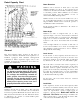
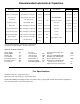
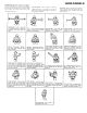
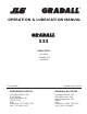

Table Of Contents
- 9020-7317 534B SERVICE MANUAL
- OPERATOR INSTRUCTIONS & LUBRICATION
- 8496 Operation & Lubrication Manual
- 8366 Operation & Lubrication Manual
- IMPORTANT SAFETY NOTICE
- INTRODUCTION
- SAFETY HIGHLIGHTS
- OPERATOR'S CAB
- CONTROL & INSTRUMENT IDENTIFICATION
- CHECKS & SERVICES BEFORE STARTING ENGINE
- ENGINE OPERATION
- WARM UP & OPERATIONAL CHECKS
- BRAKE SYSTEM
- STEERING SYSTEM
- DRIVE TRAIN
- MATERIAL HANDLING
- OPERATING PROCEDURES & TECHNIQUES
- PARKING
- STORAGE
- LUBRICATION & MAINTENANCE DIAGRAM
- 28327 Preventive Maintenance Chart
- HYDRAULIC SYSTEM
- 8497 System Operation Manual
- COVER
- NOMENCLATURE
- CAB CONTROLS AND GAGES
- ENGINE
- MAIN FRAME
- FRONT DRIVE AXLE
- DRIVE SHAFT
- REAR DRIVE AND STEERING AXLE
- TIRES
- TRANSMISSION & TORQUE CONVERTER
- STEERING CIRCUIT
- HYDRAULIC SERVICE BRAKE
- MECHANICAL PARKING BRAKE
- HYDRAULIC SYSTEM
- HYDRAULIC RESERVOIR
- HYDRAULIC PUMP
- MAIN CONTROL VALVE BANK
- MAIN PUMP CIRCUIT
- PILOT PUMP CIRCUIT
- HYDRAULIC CYLINDERS
- SWAY CIRCUIT
- LIFT CIRCUIT
- FRONT & REAR WHEEL DRIVE
- FORWARD / REVERSE LEVER (Neutral)
- FORWARD / REVERSE LEVER (Activated)
- INCHING
- TILT & COMPENSATING CIRCUITS
- OIL COOLER CIRCUIT
- CROWD (Boom In-Out) CIRCUIT
- AUXILIARY HYDRAULIC SYSTEM
- BOOM SECTIONS
- BOOM SLIDER PADS
- BOOM CROWD (IN-OUT) MOVEMENT
- MANUAL "QUICK-SWITCH" ASSEMBLY
- ELECTRICAL
- FUEL TANK
- 8369 System Operation Manual
- COVER
- NOMENCLATURE
- CAB CONTROLS AND GAGES
- ENGINE
- MAIN FRAME
- FRONT DRIVE AXLE
- DRIVE SHAFT
- REAR DRIVE AND STEERING AXLE
- TIRES
- TRANSMISSION & TORQUE CONVERTER
- STEERING CIRCUIT
- HYDRAULIC SERVICE BRAKES
- MECHANICAL PARKING BRAKE
- HYDRAULIC SYSTEM
- HYDRAULIC RESERVOIR
- HYDRAULIC PUMPS
- MAIN CONTROL VALVE BANK
- MAIN PUMP CIRCUITS
- PILOT PUMP CIRCUIT
- HYDRAULIC CYLINDERS
- SWAY CIRCUIT
- LIFT CIRCUIT
- FRONT & REAR WHEEL DRIVE
- FORWARD / REVERSE LEVER (Neutral)
- FORWARD / REVERSE LEVER (Activated)
- INCHING
- TILT & COMPENSATING CIRCUITS
- OIL COOLER CIRCUIT
- CROWD (Boom In-Out) CIRCUITS
- AUXILIARY HYDRAULIC SYSTEM
- BOOM SECTIONS
- BOOM SLIDER PADS
- BOOM CROWD (IN-OUT) MOVEMENT
- MANUAL "QUICK-SWITCH" ASSEMBLY
- ELECTRICAL
- FUEL TANK
- 81-515-009 Mico Sliding Caliper Disc Brakes Service Manual
- 81-600-001 Mico Guidelines for Installing Hydraulic Brake Components
- 81-950-016 Mico Brake Service Procedures
- 81-460-159 Mico Hydraulic Brake Valve
- 8497 System Operation Manual
- TESTING & ADJUSTING
- TROUBLE SHOOTING
- TRANSMISSION & TORQUE CONVERTER
- SM HR 182-3 Clark 18000 Series Powershift Transmission
- HOW THE UNITS OPERATE
- SECTIONAL VIEWS AND PARTS IDENTIFICATION
- DISASSEMBLY OF TRANSMISSION
- CLUTCH DISASSEMBLY
- CLEANING AND INSPECTION
- REASSEMBLY OF TRANSMISSION
- SERVICING MACHINE AFTER TRANSMISSION OVERHAUL
- TOWING OR PUSH STARTING
- SPECIFICATIONS AND SERVICE DATA
- LUBRICATION
- TROUBLESHOOTING GUIDE
- TYPICAL TWO AND THREE SPEED POWER FLOW
- PRESSURE CHECK POINTS
- CLUTCH AND GEAR ARRANGEMENT
- DRIVE PLATE INSTALLATION
- TRANSMISSION TO ENGINE INSTALLATION PROCEDURE
- SPEED SENSOR BUSHING INSTALLATION
- SM HR 182-3 Clark 18000 Series Powershift Transmission
- MISCELLANEOUS
- OPERATOR INSTRUCTIONS & LUBRICATION
Boom Extension
Numbers across bottom of chart (0' to 22') and
numbers parallel to boom (2' to 18') represent boom
extension as measured from fully retracted position
to extended position. These numbers do not reflect
total boom length, only the number of feet of
extension from fully retracted position.
Number decals on boom section number two (4, 8
12, 16 and 20) relate directly to boom extension. The
largest number which can be read from operator’s
seat indicates total boom extension.
Boom extension relates to dimension “D” shown on
serial number plate.
Boom Angle
Numbers at ends of angled fines (4° to 70°)
represent angle of boom to horizontal as measured
from horizontal plane at ground level. Maximum
angles are 4° below horizontal with boom fully
lowered to 70° above horizontal with boom fully
raised.
A boom angle indicator is located on left side of
boom section number one to show boom angle. Be
sure machine is level from front to rear or indicator
will provide incorrect reading.
Load Center
Loads shown on rated capacity chart are based on
the load center being two feet above and two feet
forward of surfaces of horizontal forks as indicated
by dimensions “B” and “C” on serial number plate.
The load center of a load is the center of gravity of
the load. For regularly shaped loads of the same
material, such as a pallet of blocks, the center of
gravity can be located by measuring the load to find
its center. For irregular loads, or loads of dissimilar
materials, keep the heaviest part of the load as close
to the heel of the forks as possible.
In all cases, the load center must be centered
between the forks.
Load Limits
Some capacities shown on the rated capacity chart
are based on machine stability and some are based
on hydraulic lift capacity. The “common sense” or
“feel” an experienced operator might apply in
regard to “tipping loads” DOES NOT APPLY to
hydraulic load limits. Exceeding load limits can
cause a relief valve to open allowing the load to fall,
or in some cases, the machine to tip over.
Rated Capacity Chart
General
The rated capacity chart, located on left side of
dashboard, indicates maximum load capacities for
handlers equipped with standard carriage/fork
combination. These capacities apply only to the
standard carriage/fork combination and cannot be
used for other attachments.
All loads shown on rated capacity chart
are based on machine being on firm, level
ground; the forks being positioned evenly
on carriage; the load being centered on
forks; proper size tires being properly
inflated; and the handler being In good
operating condition. Machines having
8000 pound capacity must have tires
properly filled with calcium chloride.
Elevation:
Numbers at left side of chart (-4' to 40') represent
elevation at heel of horizontal fork as measured
from level ground. Maximum elevation with boom
fully raised and extended is 36 feet. Elevation relates
to dimension “A” shown on serial number plate
located on right cab wall.
16