
Service Manual User Manual
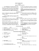
Table Of Contents
- 9020-7317 534B SERVICE MANUAL
- OPERATOR INSTRUCTIONS & LUBRICATION
- 8496 Operation & Lubrication Manual
- 8366 Operation & Lubrication Manual
- IMPORTANT SAFETY NOTICE
- INTRODUCTION
- SAFETY HIGHLIGHTS
- OPERATOR'S CAB
- CONTROL & INSTRUMENT IDENTIFICATION
- CHECKS & SERVICES BEFORE STARTING ENGINE
- ENGINE OPERATION
- WARM UP & OPERATIONAL CHECKS
- BRAKE SYSTEM
- STEERING SYSTEM
- DRIVE TRAIN
- MATERIAL HANDLING
- OPERATING PROCEDURES & TECHNIQUES
- PARKING
- STORAGE
- LUBRICATION & MAINTENANCE DIAGRAM
- 28327 Preventive Maintenance Chart
- HYDRAULIC SYSTEM
- 8497 System Operation Manual
- COVER
- NOMENCLATURE
- CAB CONTROLS AND GAGES
- ENGINE
- MAIN FRAME
- FRONT DRIVE AXLE
- DRIVE SHAFT
- REAR DRIVE AND STEERING AXLE
- TIRES
- TRANSMISSION & TORQUE CONVERTER
- STEERING CIRCUIT
- HYDRAULIC SERVICE BRAKE
- MECHANICAL PARKING BRAKE
- HYDRAULIC SYSTEM
- HYDRAULIC RESERVOIR
- HYDRAULIC PUMP
- MAIN CONTROL VALVE BANK
- MAIN PUMP CIRCUIT
- PILOT PUMP CIRCUIT
- HYDRAULIC CYLINDERS
- SWAY CIRCUIT
- LIFT CIRCUIT
- FRONT & REAR WHEEL DRIVE
- FORWARD / REVERSE LEVER (Neutral)
- FORWARD / REVERSE LEVER (Activated)
- INCHING
- TILT & COMPENSATING CIRCUITS
- OIL COOLER CIRCUIT
- CROWD (Boom In-Out) CIRCUIT
- AUXILIARY HYDRAULIC SYSTEM
- BOOM SECTIONS
- BOOM SLIDER PADS
- BOOM CROWD (IN-OUT) MOVEMENT
- MANUAL "QUICK-SWITCH" ASSEMBLY
- ELECTRICAL
- FUEL TANK
- 8369 System Operation Manual
- COVER
- NOMENCLATURE
- CAB CONTROLS AND GAGES
- ENGINE
- MAIN FRAME
- FRONT DRIVE AXLE
- DRIVE SHAFT
- REAR DRIVE AND STEERING AXLE
- TIRES
- TRANSMISSION & TORQUE CONVERTER
- STEERING CIRCUIT
- HYDRAULIC SERVICE BRAKES
- MECHANICAL PARKING BRAKE
- HYDRAULIC SYSTEM
- HYDRAULIC RESERVOIR
- HYDRAULIC PUMPS
- MAIN CONTROL VALVE BANK
- MAIN PUMP CIRCUITS
- PILOT PUMP CIRCUIT
- HYDRAULIC CYLINDERS
- SWAY CIRCUIT
- LIFT CIRCUIT
- FRONT & REAR WHEEL DRIVE
- FORWARD / REVERSE LEVER (Neutral)
- FORWARD / REVERSE LEVER (Activated)
- INCHING
- TILT & COMPENSATING CIRCUITS
- OIL COOLER CIRCUIT
- CROWD (Boom In-Out) CIRCUITS
- AUXILIARY HYDRAULIC SYSTEM
- BOOM SECTIONS
- BOOM SLIDER PADS
- BOOM CROWD (IN-OUT) MOVEMENT
- MANUAL "QUICK-SWITCH" ASSEMBLY
- ELECTRICAL
- FUEL TANK
- 81-515-009 Mico Sliding Caliper Disc Brakes Service Manual
- 81-600-001 Mico Guidelines for Installing Hydraulic Brake Components
- 81-950-016 Mico Brake Service Procedures
- 81-460-159 Mico Hydraulic Brake Valve
- 8497 System Operation Manual
- TESTING & ADJUSTING
- TROUBLE SHOOTING
- TRANSMISSION & TORQUE CONVERTER
- SM HR 182-3 Clark 18000 Series Powershift Transmission
- HOW THE UNITS OPERATE
- SECTIONAL VIEWS AND PARTS IDENTIFICATION
- DISASSEMBLY OF TRANSMISSION
- CLUTCH DISASSEMBLY
- CLEANING AND INSPECTION
- REASSEMBLY OF TRANSMISSION
- SERVICING MACHINE AFTER TRANSMISSION OVERHAUL
- TOWING OR PUSH STARTING
- SPECIFICATIONS AND SERVICE DATA
- LUBRICATION
- TROUBLESHOOTING GUIDE
- TYPICAL TWO AND THREE SPEED POWER FLOW
- PRESSURE CHECK POINTS
- CLUTCH AND GEAR ARRANGEMENT
- DRIVE PLATE INSTALLATION
- TRANSMISSION TO ENGINE INSTALLATION PROCEDURE
- SPEED SENSOR BUSHING INSTALLATION
- SM HR 182-3 Clark 18000 Series Powershift Transmission
- MISCELLANEOUS
- OPERATOR INSTRUCTIONS & LUBRICATION
The following data is presented as an aid to locating
the source of difficulty in a malfunctioning unit. It is
necessary to consider the torque converter, charging
pump, transmission, oil cooler, and connecting lines
as a complete system when running down the source
of trouble since the proper operation of any unit there-
in depends greatly on the condition and operations of
Prior to checking any part of the system from a
hydraulic standpoint, the following mechanical checks
should be made:
A check should be made to be sure all control
lever linkage is properly connected and adjusted at all
connecting points.
Before checking on the torque converter, transmis-
sion, and allied hydraulic system for pressures and
rate of oil flow, it is essential that the following pre-
liminary checks be made:
Check oil level in transmission. This should be done
with oil temperatures of 180 to 200° F. [82,2-93,3° C].
DO NOT ATTEMPT THESE CHECKS WITH COLD OIL.
To bring the oil temperature to this specification it
is necessary to either work the machine or “stall” out
Low oil level.
Clutch pressure regulating valve spool stuck open.
Faulty charging pump.
Broken or worn clutch shaft or piston sealing rings.
Clutch piston bleed valve stuck open.
Low oil level.
Suction screen plugged.
Defective oil pump.
Worn oil sealing rings.
Worn oil pump.
Low oil level.
Worn oil pump.
Worn or damaged bearings.
Low engine RPM at converter stall.
See “Overheating” and make same checks.
MECHANICAL CHECKS
HYDRAULIC CHECKS
TROUBLE SHOOTING GUIDE
LOW CLUTCH PRESSURE
HR Model. 18000 Transmission
For The
Cause
OVERHEATING
the others. By studying the principles of operation
together with data in this section, it may be possible
to correct any malfunction which may occur in the
system.
TROUBLE SHOOTING PROCEDURE BASICALLY CON-
SISTS OF TWO CLASSIFICATIONS: MECHANICAL AND
HYDRAULIC.
Check shift levers and rods for binding or restric-
tions in travel that would prevent full engagement.
Shift levers by hand at control valve, if full engage-
cover and valve assembly.
the converter. Where the former means is impractical
the latter means should be employed as follows:
Engage shift levers in forward and high speed and
apply brakes. Accelerate engine half to three-quarter
throttle.
Hold stall until desired converter outlet temperature
is reached. CAUTION: FULL THROTTLE STALL SPEEDS
FOR A EXCESSIVE LENGTH OF TIME WILL OVERHEAT
THE CONVERTER.
Remedy
Fill to proper level.
Clean valve spool and housing.
Replace pump.
Replace sealing rings.
Clean bleed valves thoroughly.
Fill to proper level.
Clean suction screen.
Replace pump.
Remove, disassemble, and rebuild converter assem-
bly.
Replace.
Fill to proper level.
Replace.
A complete disassembly will be necessary to deter-
mine what bearing is faulty.
Tune engine check governor.
Make corrections as explained in “Overheating.”
NOISY CONVERTER
LACK OF POWER
LOW CONVERTER CHARGING PUMP OUTPUT
1.
2.
3.
4.
5.
1.
2.
3.
1.
2.
3.
1.
2.
1.
2.
1.
2.
3.
4.
5.
1.
2.
3.
1.
2.
3.
1.
2.
1.
2.
1.
2.
-39-