
Service Manual User Manual
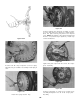
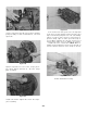
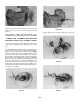
Table Of Contents
- 9020-7317 534B SERVICE MANUAL
- OPERATOR INSTRUCTIONS & LUBRICATION
- 8496 Operation & Lubrication Manual
- 8366 Operation & Lubrication Manual
- IMPORTANT SAFETY NOTICE
- INTRODUCTION
- SAFETY HIGHLIGHTS
- OPERATOR'S CAB
- CONTROL & INSTRUMENT IDENTIFICATION
- CHECKS & SERVICES BEFORE STARTING ENGINE
- ENGINE OPERATION
- WARM UP & OPERATIONAL CHECKS
- BRAKE SYSTEM
- STEERING SYSTEM
- DRIVE TRAIN
- MATERIAL HANDLING
- OPERATING PROCEDURES & TECHNIQUES
- PARKING
- STORAGE
- LUBRICATION & MAINTENANCE DIAGRAM
- 28327 Preventive Maintenance Chart
- HYDRAULIC SYSTEM
- 8497 System Operation Manual
- COVER
- NOMENCLATURE
- CAB CONTROLS AND GAGES
- ENGINE
- MAIN FRAME
- FRONT DRIVE AXLE
- DRIVE SHAFT
- REAR DRIVE AND STEERING AXLE
- TIRES
- TRANSMISSION & TORQUE CONVERTER
- STEERING CIRCUIT
- HYDRAULIC SERVICE BRAKE
- MECHANICAL PARKING BRAKE
- HYDRAULIC SYSTEM
- HYDRAULIC RESERVOIR
- HYDRAULIC PUMP
- MAIN CONTROL VALVE BANK
- MAIN PUMP CIRCUIT
- PILOT PUMP CIRCUIT
- HYDRAULIC CYLINDERS
- SWAY CIRCUIT
- LIFT CIRCUIT
- FRONT & REAR WHEEL DRIVE
- FORWARD / REVERSE LEVER (Neutral)
- FORWARD / REVERSE LEVER (Activated)
- INCHING
- TILT & COMPENSATING CIRCUITS
- OIL COOLER CIRCUIT
- CROWD (Boom In-Out) CIRCUIT
- AUXILIARY HYDRAULIC SYSTEM
- BOOM SECTIONS
- BOOM SLIDER PADS
- BOOM CROWD (IN-OUT) MOVEMENT
- MANUAL "QUICK-SWITCH" ASSEMBLY
- ELECTRICAL
- FUEL TANK
- 8369 System Operation Manual
- COVER
- NOMENCLATURE
- CAB CONTROLS AND GAGES
- ENGINE
- MAIN FRAME
- FRONT DRIVE AXLE
- DRIVE SHAFT
- REAR DRIVE AND STEERING AXLE
- TIRES
- TRANSMISSION & TORQUE CONVERTER
- STEERING CIRCUIT
- HYDRAULIC SERVICE BRAKES
- MECHANICAL PARKING BRAKE
- HYDRAULIC SYSTEM
- HYDRAULIC RESERVOIR
- HYDRAULIC PUMPS
- MAIN CONTROL VALVE BANK
- MAIN PUMP CIRCUITS
- PILOT PUMP CIRCUIT
- HYDRAULIC CYLINDERS
- SWAY CIRCUIT
- LIFT CIRCUIT
- FRONT & REAR WHEEL DRIVE
- FORWARD / REVERSE LEVER (Neutral)
- FORWARD / REVERSE LEVER (Activated)
- INCHING
- TILT & COMPENSATING CIRCUITS
- OIL COOLER CIRCUIT
- CROWD (Boom In-Out) CIRCUITS
- AUXILIARY HYDRAULIC SYSTEM
- BOOM SECTIONS
- BOOM SLIDER PADS
- BOOM CROWD (IN-OUT) MOVEMENT
- MANUAL "QUICK-SWITCH" ASSEMBLY
- ELECTRICAL
- FUEL TANK
- 81-515-009 Mico Sliding Caliper Disc Brakes Service Manual
- 81-600-001 Mico Guidelines for Installing Hydraulic Brake Components
- 81-950-016 Mico Brake Service Procedures
- 81-460-159 Mico Hydraulic Brake Valve
- 8497 System Operation Manual
- TESTING & ADJUSTING
- TROUBLE SHOOTING
- TRANSMISSION & TORQUE CONVERTER
- SM HR 182-3 Clark 18000 Series Powershift Transmission
- HOW THE UNITS OPERATE
- SECTIONAL VIEWS AND PARTS IDENTIFICATION
- DISASSEMBLY OF TRANSMISSION
- CLUTCH DISASSEMBLY
- CLEANING AND INSPECTION
- REASSEMBLY OF TRANSMISSION
- SERVICING MACHINE AFTER TRANSMISSION OVERHAUL
- TOWING OR PUSH STARTING
- SPECIFICATIONS AND SERVICE DATA
- LUBRICATION
- TROUBLESHOOTING GUIDE
- TYPICAL TWO AND THREE SPEED POWER FLOW
- PRESSURE CHECK POINTS
- CLUTCH AND GEAR ARRANGEMENT
- DRIVE PLATE INSTALLATION
- TRANSMISSION TO ENGINE INSTALLATION PROCEDURE
- SPEED SENSOR BUSHING INSTALLATION
- SM HR 182-3 Clark 18000 Series Powershift Transmission
- MISCELLANEOUS
- OPERATOR INSTRUCTIONS & LUBRICATION

The transmission, torque converter, and its allied
hydraulic system are important links in the drive line
between the engine and the wheels. The proper oper-
ation of either unit depends greatly on the condition
and operation of the other; therefore, whenever repair
or overhaul of one unit is performed, the balance of
the system must be considered before the job can be
considered completed.
After the overhauled or repaired transmission has
been installed in the machine, the oil cooler, and con-
necting hydraulic system must be thoroughly cleaned.
This can be accomplished in several manners and a de-
gree of judgment must be exercised as to the method
employed.
The following are considered the minimum steps to
be taken:
Drain engine system thoroughly.
Disconnect and clean all hydraulic lines. Where
feasible, hydraulic lines should be removed from
machine for cleaning.
Replace oil filter elements cleaning out filter
cases thoroughly.
The oil cooler must be thoroughly cleaned. The
cooler should be “back flushed” with oil and
compressed air until all foreign material has been
removed. Flushing in direction of normal oil flow
will not adequately clean the cooler. If neces-
sary, cooler assembly should be removed from
Before towing the vehicle, be sure to lift
the rear wheels off the ground or dis-
connect the driveline to avoid damage to
the transmission during towing.
SERVICING MACHINE AFTER TRANSMISSION OVERHAUL
TOWING OR PUSH STARTING
machine for cleaning, using oil, compressed air
and steam cleaner for that purpose. DO NOT
use flushing compounds for cleaning purposes.
On remote mounted torque converters remove
drain plug from torque converter and inspect
interior of converter housing, gears, etc. If
presence of considerable foreign material is
noted, disassembled and cleaned thoroughly.
It is realized this entails extra labor however
such labor is a minor cost compared to cost of
difficulties which can result from presence of
such foreign material in the system.
Reassemble all components and use only type
oil recommended in lubrication section. Fill
transmission through filler opening until fluid
comes up to LOW mark on transmission dipstick.
Run engine two minutes at 500-600 RPM to
prime torque converter and hydraulic lines. Re
check level of fluid in transmission with engine
running at idle (500-600 RPM).
Add quantity necessary to bring fluid level
to LOW mark on dipstick. Recheck with hot oil
(180-200° F.) [82, 2-93, 3° C].
Bring oil level to FULL mark on dipstick.
Recheck all drain plugs, lines, connections, etc.,
for leaks and tighten where necessary.
NOTE: If the transmission has 4 wheel
drive, disconnect both front and rear drive
lines. Because of the design of the hydrau-
lic system, the engine cannot be started by
pushing or towing.
-37-
1.
2.
3.
5.
6.
7.