
Service Manual User Manual
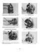
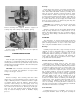
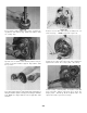
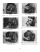

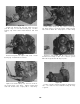
Table Of Contents
- 9020-7317 534B SERVICE MANUAL
- OPERATOR INSTRUCTIONS & LUBRICATION
- 8496 Operation & Lubrication Manual
- 8366 Operation & Lubrication Manual
- IMPORTANT SAFETY NOTICE
- INTRODUCTION
- SAFETY HIGHLIGHTS
- OPERATOR'S CAB
- CONTROL & INSTRUMENT IDENTIFICATION
- CHECKS & SERVICES BEFORE STARTING ENGINE
- ENGINE OPERATION
- WARM UP & OPERATIONAL CHECKS
- BRAKE SYSTEM
- STEERING SYSTEM
- DRIVE TRAIN
- MATERIAL HANDLING
- OPERATING PROCEDURES & TECHNIQUES
- PARKING
- STORAGE
- LUBRICATION & MAINTENANCE DIAGRAM
- 28327 Preventive Maintenance Chart
- HYDRAULIC SYSTEM
- 8497 System Operation Manual
- COVER
- NOMENCLATURE
- CAB CONTROLS AND GAGES
- ENGINE
- MAIN FRAME
- FRONT DRIVE AXLE
- DRIVE SHAFT
- REAR DRIVE AND STEERING AXLE
- TIRES
- TRANSMISSION & TORQUE CONVERTER
- STEERING CIRCUIT
- HYDRAULIC SERVICE BRAKE
- MECHANICAL PARKING BRAKE
- HYDRAULIC SYSTEM
- HYDRAULIC RESERVOIR
- HYDRAULIC PUMP
- MAIN CONTROL VALVE BANK
- MAIN PUMP CIRCUIT
- PILOT PUMP CIRCUIT
- HYDRAULIC CYLINDERS
- SWAY CIRCUIT
- LIFT CIRCUIT
- FRONT & REAR WHEEL DRIVE
- FORWARD / REVERSE LEVER (Neutral)
- FORWARD / REVERSE LEVER (Activated)
- INCHING
- TILT & COMPENSATING CIRCUITS
- OIL COOLER CIRCUIT
- CROWD (Boom In-Out) CIRCUIT
- AUXILIARY HYDRAULIC SYSTEM
- BOOM SECTIONS
- BOOM SLIDER PADS
- BOOM CROWD (IN-OUT) MOVEMENT
- MANUAL "QUICK-SWITCH" ASSEMBLY
- ELECTRICAL
- FUEL TANK
- 8369 System Operation Manual
- COVER
- NOMENCLATURE
- CAB CONTROLS AND GAGES
- ENGINE
- MAIN FRAME
- FRONT DRIVE AXLE
- DRIVE SHAFT
- REAR DRIVE AND STEERING AXLE
- TIRES
- TRANSMISSION & TORQUE CONVERTER
- STEERING CIRCUIT
- HYDRAULIC SERVICE BRAKES
- MECHANICAL PARKING BRAKE
- HYDRAULIC SYSTEM
- HYDRAULIC RESERVOIR
- HYDRAULIC PUMPS
- MAIN CONTROL VALVE BANK
- MAIN PUMP CIRCUITS
- PILOT PUMP CIRCUIT
- HYDRAULIC CYLINDERS
- SWAY CIRCUIT
- LIFT CIRCUIT
- FRONT & REAR WHEEL DRIVE
- FORWARD / REVERSE LEVER (Neutral)
- FORWARD / REVERSE LEVER (Activated)
- INCHING
- TILT & COMPENSATING CIRCUITS
- OIL COOLER CIRCUIT
- CROWD (Boom In-Out) CIRCUITS
- AUXILIARY HYDRAULIC SYSTEM
- BOOM SECTIONS
- BOOM SLIDER PADS
- BOOM CROWD (IN-OUT) MOVEMENT
- MANUAL "QUICK-SWITCH" ASSEMBLY
- ELECTRICAL
- FUEL TANK
- 81-515-009 Mico Sliding Caliper Disc Brakes Service Manual
- 81-600-001 Mico Guidelines for Installing Hydraulic Brake Components
- 81-950-016 Mico Brake Service Procedures
- 81-460-159 Mico Hydraulic Brake Valve
- 8497 System Operation Manual
- TESTING & ADJUSTING
- TROUBLE SHOOTING
- TRANSMISSION & TORQUE CONVERTER
- SM HR 182-3 Clark 18000 Series Powershift Transmission
- HOW THE UNITS OPERATE
- SECTIONAL VIEWS AND PARTS IDENTIFICATION
- DISASSEMBLY OF TRANSMISSION
- CLUTCH DISASSEMBLY
- CLEANING AND INSPECTION
- REASSEMBLY OF TRANSMISSION
- SERVICING MACHINE AFTER TRANSMISSION OVERHAUL
- TOWING OR PUSH STARTING
- SPECIFICATIONS AND SERVICE DATA
- LUBRICATION
- TROUBLESHOOTING GUIDE
- TYPICAL TWO AND THREE SPEED POWER FLOW
- PRESSURE CHECK POINTS
- CLUTCH AND GEAR ARRANGEMENT
- DRIVE PLATE INSTALLATION
- TRANSMISSION TO ENGINE INSTALLATION PROCEDURE
- SPEED SENSOR BUSHING INSTALLATION
- SM HR 182-3 Clark 18000 Series Powershift Transmission
- MISCELLANEOUS
- OPERATOR INSTRUCTIONS & LUBRICATION
Housings
Clean interior and exterior of housings, bearing caps,
etc., thoroughly. Cast parts may be cleaned in hot sol-
ution tanks with mild alkali solutions providing these
parts do not have ground or polished surfaces. Parts
should remain in solution long enough to be thorough-
ly cleaned and heated This will aid the evaporation of
the cleaning solution and rinse water. Parts cleaned
in solution tanks must be thoroughly rinsed with clean
water to remove all traces of alkali. Cast parts may also
be cleaned with steam cleaner.
CAUTION: Care should be exercised to avoid skin
rashes and inhalation of vapors when using alkali
cleaners.
All parts cleaned must be thoroughly dried immedi-
ately by using moisture-free compressed air or soft,
lintless absorbent wiping rags free of abrasive materi-
als such as metal filings, contaminated oil or lapping
compound.
INSPECTION
The importance of careful and thorough inspection
all parts cannot be overstressed. Replacement of all
parts showing indication of wear or stress will elimi-
nate costly and avoidable failures at a later date.
Bearings
Carefully inspect all rollers, cages and cups for wear,
chipping or nicks to determine fitness of bearings for
further use. Do not replace a bearing cone or cup
individually without replacing the mating cup or cone
at the same time After inspection dip bearings in
clean light oil and wrap in clean lintless cloth or paper
to protect them until installed.
Oil Seals, Gaskets and Retaining Rings
Replacement of spring load oil seals, “O” rings,
metal sealing rings, gaskets and snap rings is more
economical when unit is disassembled than premature
overhaul to replace these parts at a future time. Fur-
ther loss of lubricant through a worn seal may result
in failure of other more expensive parts of the assem-
bly. Sealing members should be handled carefully
particularly when being installed. Cutting, scratching
or curling under of lip of seal seriously impairs its
efficiency. Apply a thin coat of Permatex No. 2 on
the outer diameter of the oil seal to assure an oil tight
fit into the retainer. When assembling new metal type
sealing rings, same should be lubricated with coat of
chassis grease to stabilize rings in their grooves for
ease of assembly of meeting members. Lubricate all
“O” rings and seals with recommended type Automatic
Transmission Fluid before assembly.
Gears and Shafts
If magna-flux process is available, use process to
check parts Examine teeth on all gears carefully for
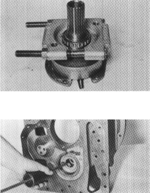
Figure 124
If reverse clutch piston ring sleeve is to be replaced,
remove as shown.
CLEANING AND INSPECTION
CLEANING
Clean all parts thoroughly using solvent type clean-
ing fluid. It is recommended that parts be immersed in
cleaning fluid and moved up and down slowly until all
old lubricant and foreign material is dissolved and parts
are thoroughly cleaned.
CAUTION: Care should be exercised to avoid skin
rashes, fire hazards and inhalation of vapors when
using solvent type cleaners.
Bearings
Remove bearings from cleaning fluid and strike
larger side of cone flat against a block of wood to dis-
lodge solidified particles of lubricant. Immerse again
in cleaning fluid to flush out particles. Repeat above
operation until bearings are thoroughly clean. Dry
bearings using moisture-free compressed air. Be care-
ful to direct air stream across bearing to avoid spin-
ning. Do not spin bearings when drying. Bearings
may be rotated slowly by hand to facilitate drying
process.
Figure 123
Remove bearing from support. Remove support oil
sealing ring and sealing ring expander spring.
-22-