
Service Manual User Manual
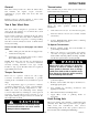
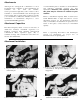
Table Of Contents
- 9020-7317 534B SERVICE MANUAL
- OPERATOR INSTRUCTIONS & LUBRICATION
- 8496 Operation & Lubrication Manual
- 8366 Operation & Lubrication Manual
- IMPORTANT SAFETY NOTICE
- INTRODUCTION
- SAFETY HIGHLIGHTS
- OPERATOR'S CAB
- CONTROL & INSTRUMENT IDENTIFICATION
- CHECKS & SERVICES BEFORE STARTING ENGINE
- ENGINE OPERATION
- WARM UP & OPERATIONAL CHECKS
- BRAKE SYSTEM
- STEERING SYSTEM
- DRIVE TRAIN
- MATERIAL HANDLING
- OPERATING PROCEDURES & TECHNIQUES
- PARKING
- STORAGE
- LUBRICATION & MAINTENANCE DIAGRAM
- 28327 Preventive Maintenance Chart
- HYDRAULIC SYSTEM
- 8497 System Operation Manual
- COVER
- NOMENCLATURE
- CAB CONTROLS AND GAGES
- ENGINE
- MAIN FRAME
- FRONT DRIVE AXLE
- DRIVE SHAFT
- REAR DRIVE AND STEERING AXLE
- TIRES
- TRANSMISSION & TORQUE CONVERTER
- STEERING CIRCUIT
- HYDRAULIC SERVICE BRAKE
- MECHANICAL PARKING BRAKE
- HYDRAULIC SYSTEM
- HYDRAULIC RESERVOIR
- HYDRAULIC PUMP
- MAIN CONTROL VALVE BANK
- MAIN PUMP CIRCUIT
- PILOT PUMP CIRCUIT
- HYDRAULIC CYLINDERS
- SWAY CIRCUIT
- LIFT CIRCUIT
- FRONT & REAR WHEEL DRIVE
- FORWARD / REVERSE LEVER (Neutral)
- FORWARD / REVERSE LEVER (Activated)
- INCHING
- TILT & COMPENSATING CIRCUITS
- OIL COOLER CIRCUIT
- CROWD (Boom In-Out) CIRCUIT
- AUXILIARY HYDRAULIC SYSTEM
- BOOM SECTIONS
- BOOM SLIDER PADS
- BOOM CROWD (IN-OUT) MOVEMENT
- MANUAL "QUICK-SWITCH" ASSEMBLY
- ELECTRICAL
- FUEL TANK
- 8369 System Operation Manual
- COVER
- NOMENCLATURE
- CAB CONTROLS AND GAGES
- ENGINE
- MAIN FRAME
- FRONT DRIVE AXLE
- DRIVE SHAFT
- REAR DRIVE AND STEERING AXLE
- TIRES
- TRANSMISSION & TORQUE CONVERTER
- STEERING CIRCUIT
- HYDRAULIC SERVICE BRAKES
- MECHANICAL PARKING BRAKE
- HYDRAULIC SYSTEM
- HYDRAULIC RESERVOIR
- HYDRAULIC PUMPS
- MAIN CONTROL VALVE BANK
- MAIN PUMP CIRCUITS
- PILOT PUMP CIRCUIT
- HYDRAULIC CYLINDERS
- SWAY CIRCUIT
- LIFT CIRCUIT
- FRONT & REAR WHEEL DRIVE
- FORWARD / REVERSE LEVER (Neutral)
- FORWARD / REVERSE LEVER (Activated)
- INCHING
- TILT & COMPENSATING CIRCUITS
- OIL COOLER CIRCUIT
- CROWD (Boom In-Out) CIRCUITS
- AUXILIARY HYDRAULIC SYSTEM
- BOOM SECTIONS
- BOOM SLIDER PADS
- BOOM CROWD (IN-OUT) MOVEMENT
- MANUAL "QUICK-SWITCH" ASSEMBLY
- ELECTRICAL
- FUEL TANK
- 81-515-009 Mico Sliding Caliper Disc Brakes Service Manual
- 81-600-001 Mico Guidelines for Installing Hydraulic Brake Components
- 81-950-016 Mico Brake Service Procedures
- 81-460-159 Mico Hydraulic Brake Valve
- 8497 System Operation Manual
- TESTING & ADJUSTING
- TROUBLE SHOOTING
- TRANSMISSION & TORQUE CONVERTER
- SM HR 182-3 Clark 18000 Series Powershift Transmission
- HOW THE UNITS OPERATE
- SECTIONAL VIEWS AND PARTS IDENTIFICATION
- DISASSEMBLY OF TRANSMISSION
- CLUTCH DISASSEMBLY
- CLEANING AND INSPECTION
- REASSEMBLY OF TRANSMISSION
- SERVICING MACHINE AFTER TRANSMISSION OVERHAUL
- TOWING OR PUSH STARTING
- SPECIFICATIONS AND SERVICE DATA
- LUBRICATION
- TROUBLESHOOTING GUIDE
- TYPICAL TWO AND THREE SPEED POWER FLOW
- PRESSURE CHECK POINTS
- CLUTCH AND GEAR ARRANGEMENT
- DRIVE PLATE INSTALLATION
- TRANSMISSION TO ENGINE INSTALLATION PROCEDURE
- SPEED SENSOR BUSHING INSTALLATION
- SM HR 182-3 Clark 18000 Series Powershift Transmission
- MISCELLANEOUS
- OPERATOR INSTRUCTIONS & LUBRICATION
The drive train provides two and four wheel drive
and includes the engine, torque converter,
transmission, propel shaft and front and rear
driving axles.
Inching travel is directly related to drive train
functions and will be discussed in this section.
Two & Four Wheel Drive
The drive train is designed to provide two wheel
drive (front axle driving) or tour wheel drive (both
front and rear axles driving).
Under certain conditions, changing from four wheel
drive to two wheel drive may cause a difference in
the way the machine responds to steering, braking
and drive controls. Always be aware of which travel
mode you are using.
There are two ways to disengage rear wheel
drive:
NOTE: Rear drive axle can also be disengaged in
response to overload in associated electrical
circuitry causing automatic reset type circuit
breaker to trip (open). Breaker will close again in
approximately ten seconds.
Torque Converter
There are no operator controls for the torque
converter. It functions automatically to permit
starting from a standstill in any transmission speed
range.
An oil temperature gage is provided to indicate
operating temperature of torque converter/trans-
mission. Normal operating temperature is 180 -
200°F. (82 - 93°C.). If overheating occurs, attempt
to lower temperature by traveling in a lower gear. If
necessary, stop and allow torque converter to cool
with engine running and gear selector in neutral. Be
sure radiator fins are clean.
Front Driving Axle
The front driving axle includes a differential and
planetary drive hubs and is powered by a propeller
shaft from the transmission. The service
brake/inching pedal is the only operator control for
the front axle (refer to Inching travel Heading).
DRIVE TRAIN
Transmission
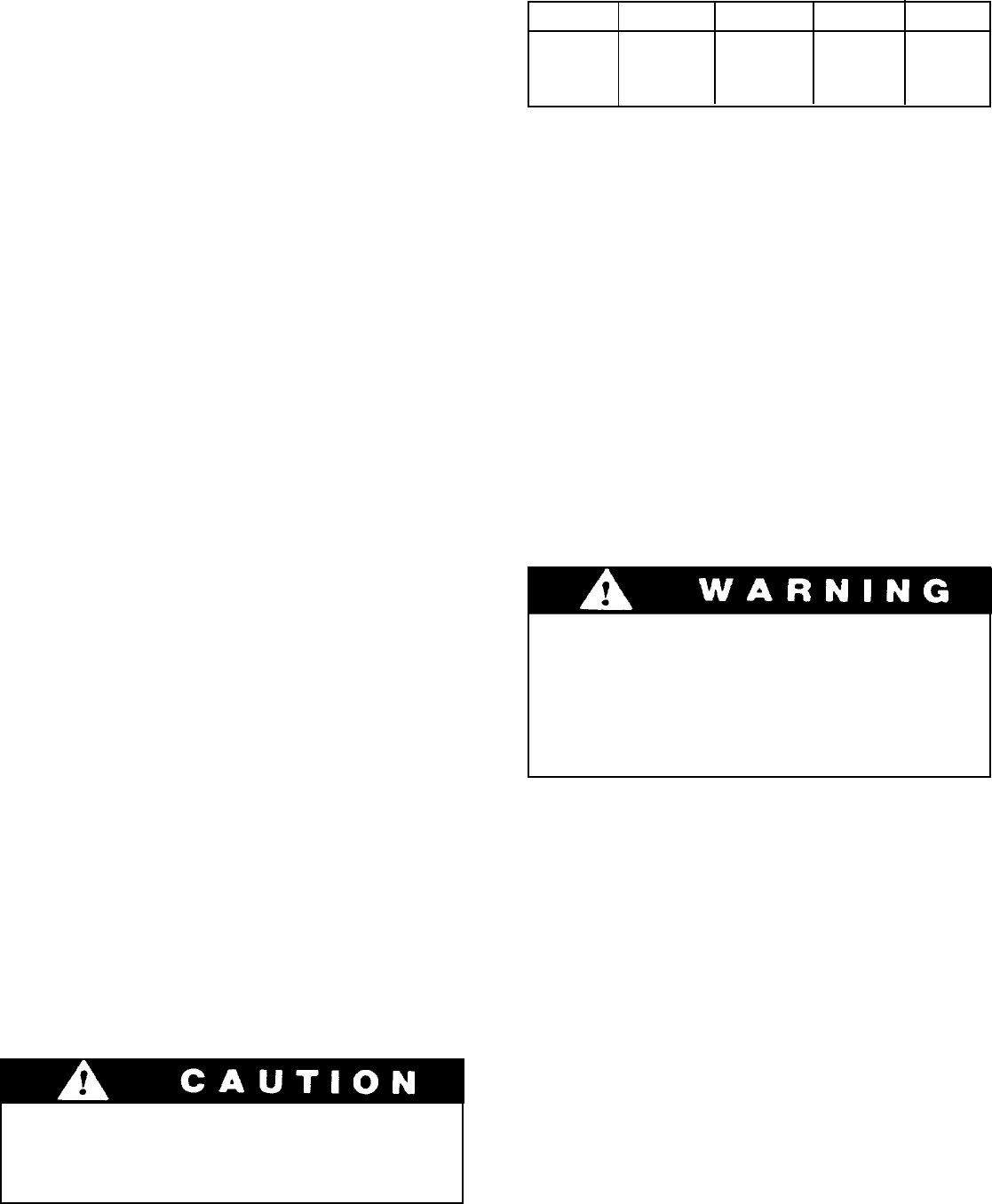
The transmission provides three speed ranges for
both forward and reverse travel.
General
Shift to third gear (rear axle drive is engaged only
in first and second gears)
Disengage rear planetary hubs (refer to Rear
Drive Axle heading in this section)
1.
2.
Continued operation of overheated torque
converter/transmission can cause serious
damage to these components.
11
Gear 1st 2nd 3rd 3rd*
mph 2.8 6.0 15.9 17.9
kmph 4.5 9.6 25.6 28.8
*With rear planetary hubs disengaged
There are three operator controls for the
transmission:
Gear Selector Lever (for 1st, 2nd and 3rd gears)
Direction Selector Lever (for forward, neutral
and reverse)
Service Brake/Inching Pedal (refer to Inching
Travel heading in this section)
1.
2.
3.
To Operate Transmission:
Release parking brake and hold handler in
position using service brake.
Move gear selector to appropriate speed range
(1st, 2nd or 3rd gear). The gear selector may be
shifted while traveling. When traveling downhill,
use the same gear needed to travel up the hill.
1.
2.
Never shift gear selector or direction
selector to cause a sudden change of
travel speed or direction. Such a change
could cause load to shift or machine to tip
over. Reversing direction while traveling
can also damage transmission.
Move direction selector to forward or reverse
position as required.
Release service brake and depress accelerator to
attain appropriate speed.
Stop handler by releasing accelerator and
applying service brake.
Move direction selector to neutral position.
Apply Mico Lock or parking brake as
appropriate.
3.
4.
5.
6.
7.
contined...