
Service Manual User Manual


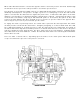
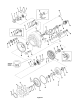
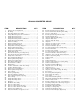
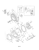
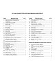
Table Of Contents
- 9020-7317 534B SERVICE MANUAL
- OPERATOR INSTRUCTIONS & LUBRICATION
- 8496 Operation & Lubrication Manual
- 8366 Operation & Lubrication Manual
- IMPORTANT SAFETY NOTICE
- INTRODUCTION
- SAFETY HIGHLIGHTS
- OPERATOR'S CAB
- CONTROL & INSTRUMENT IDENTIFICATION
- CHECKS & SERVICES BEFORE STARTING ENGINE
- ENGINE OPERATION
- WARM UP & OPERATIONAL CHECKS
- BRAKE SYSTEM
- STEERING SYSTEM
- DRIVE TRAIN
- MATERIAL HANDLING
- OPERATING PROCEDURES & TECHNIQUES
- PARKING
- STORAGE
- LUBRICATION & MAINTENANCE DIAGRAM
- 28327 Preventive Maintenance Chart
- HYDRAULIC SYSTEM
- 8497 System Operation Manual
- COVER
- NOMENCLATURE
- CAB CONTROLS AND GAGES
- ENGINE
- MAIN FRAME
- FRONT DRIVE AXLE
- DRIVE SHAFT
- REAR DRIVE AND STEERING AXLE
- TIRES
- TRANSMISSION & TORQUE CONVERTER
- STEERING CIRCUIT
- HYDRAULIC SERVICE BRAKE
- MECHANICAL PARKING BRAKE
- HYDRAULIC SYSTEM
- HYDRAULIC RESERVOIR
- HYDRAULIC PUMP
- MAIN CONTROL VALVE BANK
- MAIN PUMP CIRCUIT
- PILOT PUMP CIRCUIT
- HYDRAULIC CYLINDERS
- SWAY CIRCUIT
- LIFT CIRCUIT
- FRONT & REAR WHEEL DRIVE
- FORWARD / REVERSE LEVER (Neutral)
- FORWARD / REVERSE LEVER (Activated)
- INCHING
- TILT & COMPENSATING CIRCUITS
- OIL COOLER CIRCUIT
- CROWD (Boom In-Out) CIRCUIT
- AUXILIARY HYDRAULIC SYSTEM
- BOOM SECTIONS
- BOOM SLIDER PADS
- BOOM CROWD (IN-OUT) MOVEMENT
- MANUAL "QUICK-SWITCH" ASSEMBLY
- ELECTRICAL
- FUEL TANK
- 8369 System Operation Manual
- COVER
- NOMENCLATURE
- CAB CONTROLS AND GAGES
- ENGINE
- MAIN FRAME
- FRONT DRIVE AXLE
- DRIVE SHAFT
- REAR DRIVE AND STEERING AXLE
- TIRES
- TRANSMISSION & TORQUE CONVERTER
- STEERING CIRCUIT
- HYDRAULIC SERVICE BRAKES
- MECHANICAL PARKING BRAKE
- HYDRAULIC SYSTEM
- HYDRAULIC RESERVOIR
- HYDRAULIC PUMPS
- MAIN CONTROL VALVE BANK
- MAIN PUMP CIRCUITS
- PILOT PUMP CIRCUIT
- HYDRAULIC CYLINDERS
- SWAY CIRCUIT
- LIFT CIRCUIT
- FRONT & REAR WHEEL DRIVE
- FORWARD / REVERSE LEVER (Neutral)
- FORWARD / REVERSE LEVER (Activated)
- INCHING
- TILT & COMPENSATING CIRCUITS
- OIL COOLER CIRCUIT
- CROWD (Boom In-Out) CIRCUITS
- AUXILIARY HYDRAULIC SYSTEM
- BOOM SECTIONS
- BOOM SLIDER PADS
- BOOM CROWD (IN-OUT) MOVEMENT
- MANUAL "QUICK-SWITCH" ASSEMBLY
- ELECTRICAL
- FUEL TANK
- 81-515-009 Mico Sliding Caliper Disc Brakes Service Manual
- 81-600-001 Mico Guidelines for Installing Hydraulic Brake Components
- 81-950-016 Mico Brake Service Procedures
- 81-460-159 Mico Hydraulic Brake Valve
- 8497 System Operation Manual
- TESTING & ADJUSTING
- TROUBLE SHOOTING
- TRANSMISSION & TORQUE CONVERTER
- SM HR 182-3 Clark 18000 Series Powershift Transmission
- HOW THE UNITS OPERATE
- SECTIONAL VIEWS AND PARTS IDENTIFICATION
- DISASSEMBLY OF TRANSMISSION
- CLUTCH DISASSEMBLY
- CLEANING AND INSPECTION
- REASSEMBLY OF TRANSMISSION
- SERVICING MACHINE AFTER TRANSMISSION OVERHAUL
- TOWING OR PUSH STARTING
- SPECIFICATIONS AND SERVICE DATA
- LUBRICATION
- TROUBLESHOOTING GUIDE
- TYPICAL TWO AND THREE SPEED POWER FLOW
- PRESSURE CHECK POINTS
- CLUTCH AND GEAR ARRANGEMENT
- DRIVE PLATE INSTALLATION
- TRANSMISSION TO ENGINE INSTALLATION PROCEDURE
- SPEED SENSOR BUSHING INSTALLATION
- SM HR 182-3 Clark 18000 Series Powershift Transmission
- MISCELLANEOUS
- OPERATOR INSTRUCTIONS & LUBRICATION
With the engine running, the converter charging pump draws oil from the transmission sump through the
removable oil suction screen and directs it through the pressure regulating valve and oil filter.
The pressure regulating valve maintains pressure to the transmission control cover for actuating the direc-
tion and speed clutches. This requires a small portion of the total volume of oil used in the system. The
remaining volume of oil is directed through the torque converter circuit to the oil cooler and returns to
the transmission for positive lubrication. This regulator valve consists of a hardened valve spool operating
in a closely fitted bore. The valve spool is spring loaded to hold the valve in a closed position. When a
specific pressure is achieved, the valve spool works against the spring until a port is exposed along the
side of the bore. This sequence of events provides the proper system pressure.
After entering the converter housing the oil is directed through the stator support to the converter blade
cavity and exits in the passage between the turbine shaft and converter support. The oil then flows out of
the converter to the oil cooler. After leaving the cooler, the oil is directed to a lubricating fitting on the
transmission and through a series of tubes and passages lubricates the transmission bearings and clutches.
The oil then gravity drains to the transmission sump.
The hydraulic torque converter consists basically of three elements and their related parts to multiply engine
torque. The engine power is transmitted from the engine flywheel to the impeller element through the
impeller cover. This element is the pump portion of the hydraulic torque converter and is the primary com-
ponent which starts the oil flowing to the other components which results in torque multiplication. This el-
ement can be compared to a centrifugal pump in that it picks up fluid at its center and discharges at its outer
diameter.
The torque converter turbine is mounted opposite the impeller and is connected to the output shaft of the
torque converter. This element receives fluid at its outer diameter and discharges at its center. Fluid directed
by the impeller out into the particular design of blading in the turbine and reaction member is the means
by which the hydraulic torque converter multiplies torque.
The reaction member of the torque converter is located between and at the center or inner diameters of the
impeller and turbine elements. Its function is to take the fluid which is exhausting from the inner portion
of the turbine and change its direction to allow correct entry for recirculation into the impeller element.
The torque converter will multiply engine torque to its designed maximum multiplication ratio when the out-
put shaft is at zero RPM. Therefore, we can say that as the output shaft is decreasing in speed the torque
multiplication is increasing.
The shift control valve assembly consists of a valve body with selector valve spools. A detent ball and spring
in the selector spool provides one position for each speed range. A detent ball and spring in the direction
spool provides three positions, one each for forward, neutral and reverse.
With the engine running and the directional control lever in neutral position, oil pressure from the regulat-
ing valve is blocked at the control valve, and the transmission is in neutral. Movement of the forward and
reverse spool will direct oil, under pressure to either the forward or reverse direction clutch as desired.