
Service Manual User Manual
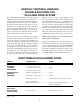
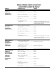
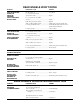
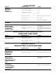
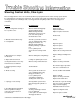
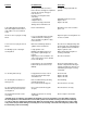
Table Of Contents
- 9020-7317 534B SERVICE MANUAL
- OPERATOR INSTRUCTIONS & LUBRICATION
- 8496 Operation & Lubrication Manual
- 8366 Operation & Lubrication Manual
- IMPORTANT SAFETY NOTICE
- INTRODUCTION
- SAFETY HIGHLIGHTS
- OPERATOR'S CAB
- CONTROL & INSTRUMENT IDENTIFICATION
- CHECKS & SERVICES BEFORE STARTING ENGINE
- ENGINE OPERATION
- WARM UP & OPERATIONAL CHECKS
- BRAKE SYSTEM
- STEERING SYSTEM
- DRIVE TRAIN
- MATERIAL HANDLING
- OPERATING PROCEDURES & TECHNIQUES
- PARKING
- STORAGE
- LUBRICATION & MAINTENANCE DIAGRAM
- 28327 Preventive Maintenance Chart
- HYDRAULIC SYSTEM
- 8497 System Operation Manual
- COVER
- NOMENCLATURE
- CAB CONTROLS AND GAGES
- ENGINE
- MAIN FRAME
- FRONT DRIVE AXLE
- DRIVE SHAFT
- REAR DRIVE AND STEERING AXLE
- TIRES
- TRANSMISSION & TORQUE CONVERTER
- STEERING CIRCUIT
- HYDRAULIC SERVICE BRAKE
- MECHANICAL PARKING BRAKE
- HYDRAULIC SYSTEM
- HYDRAULIC RESERVOIR
- HYDRAULIC PUMP
- MAIN CONTROL VALVE BANK
- MAIN PUMP CIRCUIT
- PILOT PUMP CIRCUIT
- HYDRAULIC CYLINDERS
- SWAY CIRCUIT
- LIFT CIRCUIT
- FRONT & REAR WHEEL DRIVE
- FORWARD / REVERSE LEVER (Neutral)
- FORWARD / REVERSE LEVER (Activated)
- INCHING
- TILT & COMPENSATING CIRCUITS
- OIL COOLER CIRCUIT
- CROWD (Boom In-Out) CIRCUIT
- AUXILIARY HYDRAULIC SYSTEM
- BOOM SECTIONS
- BOOM SLIDER PADS
- BOOM CROWD (IN-OUT) MOVEMENT
- MANUAL "QUICK-SWITCH" ASSEMBLY
- ELECTRICAL
- FUEL TANK
- 8369 System Operation Manual
- COVER
- NOMENCLATURE
- CAB CONTROLS AND GAGES
- ENGINE
- MAIN FRAME
- FRONT DRIVE AXLE
- DRIVE SHAFT
- REAR DRIVE AND STEERING AXLE
- TIRES
- TRANSMISSION & TORQUE CONVERTER
- STEERING CIRCUIT
- HYDRAULIC SERVICE BRAKES
- MECHANICAL PARKING BRAKE
- HYDRAULIC SYSTEM
- HYDRAULIC RESERVOIR
- HYDRAULIC PUMPS
- MAIN CONTROL VALVE BANK
- MAIN PUMP CIRCUITS
- PILOT PUMP CIRCUIT
- HYDRAULIC CYLINDERS
- SWAY CIRCUIT
- LIFT CIRCUIT
- FRONT & REAR WHEEL DRIVE
- FORWARD / REVERSE LEVER (Neutral)
- FORWARD / REVERSE LEVER (Activated)
- INCHING
- TILT & COMPENSATING CIRCUITS
- OIL COOLER CIRCUIT
- CROWD (Boom In-Out) CIRCUITS
- AUXILIARY HYDRAULIC SYSTEM
- BOOM SECTIONS
- BOOM SLIDER PADS
- BOOM CROWD (IN-OUT) MOVEMENT
- MANUAL "QUICK-SWITCH" ASSEMBLY
- ELECTRICAL
- FUEL TANK
- 81-515-009 Mico Sliding Caliper Disc Brakes Service Manual
- 81-600-001 Mico Guidelines for Installing Hydraulic Brake Components
- 81-950-016 Mico Brake Service Procedures
- 81-460-159 Mico Hydraulic Brake Valve
- 8497 System Operation Manual
- TESTING & ADJUSTING
- TROUBLE SHOOTING
- TRANSMISSION & TORQUE CONVERTER
- SM HR 182-3 Clark 18000 Series Powershift Transmission
- HOW THE UNITS OPERATE
- SECTIONAL VIEWS AND PARTS IDENTIFICATION
- DISASSEMBLY OF TRANSMISSION
- CLUTCH DISASSEMBLY
- CLEANING AND INSPECTION
- REASSEMBLY OF TRANSMISSION
- SERVICING MACHINE AFTER TRANSMISSION OVERHAUL
- TOWING OR PUSH STARTING
- SPECIFICATIONS AND SERVICE DATA
- LUBRICATION
- TROUBLESHOOTING GUIDE
- TYPICAL TWO AND THREE SPEED POWER FLOW
- PRESSURE CHECK POINTS
- CLUTCH AND GEAR ARRANGEMENT
- DRIVE PLATE INSTALLATION
- TRANSMISSION TO ENGINE INSTALLATION PROCEDURE
- SPEED SENSOR BUSHING INSTALLATION
- SM HR 182-3 Clark 18000 Series Powershift Transmission
- MISCELLANEOUS
- OPERATOR INSTRUCTIONS & LUBRICATION

Problem
9. Free Wheeling-Steering wheel
turns with slight resistance but re-
sults in little or no steered wheel
action.
10. Excessive free play at steering
wheel.
11. Excessive free play at steered
wheels.
12. Binding or poor centering of
steering wheel.
13. Steering unit locks up.
14. Steering wheel oscillates or
turns by itself.
15. Steered wheels turn in wrong
direction when operator activates
steering wheel
16.Steering wheel kicks at start
of steering.
Possible Cause
Steering control unit meter has a
lack of oil. This can happen on problem.
start-up, after repair, or long per-
iods of non use.
No flow to steering unit can be
caused by:
1. Low fluid level.
2. Ruptured hose.
3. Internal steering control unit
damage due to thermal shock*.
Piston seal blown out.
Loose steering wheel nut. Steering
column shaft worn or damaged.
There should be very little free play
in the unit itself.
Broken or worn linkage between
cylinder and steered wheels.
Leaky cylinder seals.
Binding or misalignment in steer-
ing column or splined input con-
nection.
High back pressure in tank line can
cause slow return to center. Should
not exceed 300 psi.
Large particles can cause binding
between the spool and sleeve (in
Orbitrol).
Large particles in meter section.
Severe wear and/or broken pin.
*Thermal shock.
Parts assembled wrong. Steering
unit improperly timed.
Lines connected to wrong ports.
Lines connected to wrong cylin-
der ports.
Sticking check valve on steering
control unit.
Correction
Usually starting engine will cure
problem.
Add fluid and check for leaks.
Replace hose.
Replace the unit.
Determine cause. Correct and re-
place seal.
Repair or replace steering wheel con-
nection or column.
Check for loose fitting bearings and
anchor points in steering linkage be-
tween cylinder and steered wheels.
Replace cylinder seals.
Align column pilot and spline to
steering control unit.
Check for restriction.
Clean the unit and filter the oil. If
another component has failed gen-
erating contaminents, flush the sys-
tem while bypassing the steering
control unit.
Clean the unit.
Replace the unit.
Replace the unit.
Correct timing.
Reconnect lines correctly.
Reconnect lines correctly.
Clean or replace check valve.
*Thermal shock-A condition caused when the hydraulic system is operated for some time without turning
the steering wheel so that fluid in the reservoir and system is hot and the steering control unit is relatively
cool (more than 50°F temperature differential). When the steering wheel is turned quickly the result is temp
orary seizure and possible damage to internal parts of the steering control unit. The temperary seizure may
be followed by total free wheeling.