
Service Manual User Manual
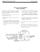
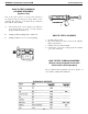
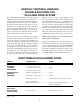
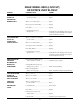
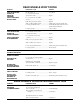
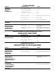
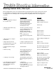
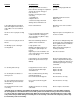
Table Of Contents
- 9020-7317 534B SERVICE MANUAL
- OPERATOR INSTRUCTIONS & LUBRICATION
- 8496 Operation & Lubrication Manual
- 8366 Operation & Lubrication Manual
- IMPORTANT SAFETY NOTICE
- INTRODUCTION
- SAFETY HIGHLIGHTS
- OPERATOR'S CAB
- CONTROL & INSTRUMENT IDENTIFICATION
- CHECKS & SERVICES BEFORE STARTING ENGINE
- ENGINE OPERATION
- WARM UP & OPERATIONAL CHECKS
- BRAKE SYSTEM
- STEERING SYSTEM
- DRIVE TRAIN
- MATERIAL HANDLING
- OPERATING PROCEDURES & TECHNIQUES
- PARKING
- STORAGE
- LUBRICATION & MAINTENANCE DIAGRAM
- 28327 Preventive Maintenance Chart
- HYDRAULIC SYSTEM
- 8497 System Operation Manual
- COVER
- NOMENCLATURE
- CAB CONTROLS AND GAGES
- ENGINE
- MAIN FRAME
- FRONT DRIVE AXLE
- DRIVE SHAFT
- REAR DRIVE AND STEERING AXLE
- TIRES
- TRANSMISSION & TORQUE CONVERTER
- STEERING CIRCUIT
- HYDRAULIC SERVICE BRAKE
- MECHANICAL PARKING BRAKE
- HYDRAULIC SYSTEM
- HYDRAULIC RESERVOIR
- HYDRAULIC PUMP
- MAIN CONTROL VALVE BANK
- MAIN PUMP CIRCUIT
- PILOT PUMP CIRCUIT
- HYDRAULIC CYLINDERS
- SWAY CIRCUIT
- LIFT CIRCUIT
- FRONT & REAR WHEEL DRIVE
- FORWARD / REVERSE LEVER (Neutral)
- FORWARD / REVERSE LEVER (Activated)
- INCHING
- TILT & COMPENSATING CIRCUITS
- OIL COOLER CIRCUIT
- CROWD (Boom In-Out) CIRCUIT
- AUXILIARY HYDRAULIC SYSTEM
- BOOM SECTIONS
- BOOM SLIDER PADS
- BOOM CROWD (IN-OUT) MOVEMENT
- MANUAL "QUICK-SWITCH" ASSEMBLY
- ELECTRICAL
- FUEL TANK
- 8369 System Operation Manual
- COVER
- NOMENCLATURE
- CAB CONTROLS AND GAGES
- ENGINE
- MAIN FRAME
- FRONT DRIVE AXLE
- DRIVE SHAFT
- REAR DRIVE AND STEERING AXLE
- TIRES
- TRANSMISSION & TORQUE CONVERTER
- STEERING CIRCUIT
- HYDRAULIC SERVICE BRAKES
- MECHANICAL PARKING BRAKE
- HYDRAULIC SYSTEM
- HYDRAULIC RESERVOIR
- HYDRAULIC PUMPS
- MAIN CONTROL VALVE BANK
- MAIN PUMP CIRCUITS
- PILOT PUMP CIRCUIT
- HYDRAULIC CYLINDERS
- SWAY CIRCUIT
- LIFT CIRCUIT
- FRONT & REAR WHEEL DRIVE
- FORWARD / REVERSE LEVER (Neutral)
- FORWARD / REVERSE LEVER (Activated)
- INCHING
- TILT & COMPENSATING CIRCUITS
- OIL COOLER CIRCUIT
- CROWD (Boom In-Out) CIRCUITS
- AUXILIARY HYDRAULIC SYSTEM
- BOOM SECTIONS
- BOOM SLIDER PADS
- BOOM CROWD (IN-OUT) MOVEMENT
- MANUAL "QUICK-SWITCH" ASSEMBLY
- ELECTRICAL
- FUEL TANK
- 81-515-009 Mico Sliding Caliper Disc Brakes Service Manual
- 81-600-001 Mico Guidelines for Installing Hydraulic Brake Components
- 81-950-016 Mico Brake Service Procedures
- 81-460-159 Mico Hydraulic Brake Valve
- 8497 System Operation Manual
- TESTING & ADJUSTING
- TROUBLE SHOOTING
- TRANSMISSION & TORQUE CONVERTER
- SM HR 182-3 Clark 18000 Series Powershift Transmission
- HOW THE UNITS OPERATE
- SECTIONAL VIEWS AND PARTS IDENTIFICATION
- DISASSEMBLY OF TRANSMISSION
- CLUTCH DISASSEMBLY
- CLEANING AND INSPECTION
- REASSEMBLY OF TRANSMISSION
- SERVICING MACHINE AFTER TRANSMISSION OVERHAUL
- TOWING OR PUSH STARTING
- SPECIFICATIONS AND SERVICE DATA
- LUBRICATION
- TROUBLESHOOTING GUIDE
- TYPICAL TWO AND THREE SPEED POWER FLOW
- PRESSURE CHECK POINTS
- CLUTCH AND GEAR ARRANGEMENT
- DRIVE PLATE INSTALLATION
- TRANSMISSION TO ENGINE INSTALLATION PROCEDURE
- SPEED SENSOR BUSHING INSTALLATION
- SM HR 182-3 Clark 18000 Series Powershift Transmission
- MISCELLANEOUS
- OPERATOR INSTRUCTIONS & LUBRICATION

Problem
1. Slow steering, hard steering, or
loss of power assist.
2. Wander-Vehicle will not stay
in a straight line.
3. Drift-Vehicle veers slowly in
one direction.
4. Slip-A slow movement of
steering wheel fails to cause any
movement of steered wheels.
5. Temporary hard steering or
hang-up.
6. Erratic steering.
7. “Spongy” or soft steering.
8. Free Wheeling-Steering wheel
turns freely with no feeling of
of pressure and no action on
steered wheels.
Steering Control Units, Char-Lynn
Most steering problems can be corrected if the problem is properly defined. The entire steering system should
be evaluated before removing any components. The steering control unit is generally not the cause of most
steering problems. The following is a list of steering problems along with possible causes and suggested
corrections.
Possible Cause
Worn or malfunctioning pump.
Stuck flow divider piston.
Malfunctioning relief valve
allowing the system pressure
to be less than specified.
Overloaded steer axle.
Air in the system due to low lev-
el of oil, cavitating pump, leaky
fitting, pinched hose, etc.
Worn mechanical linkage.
Bending of linkage or cylinder
rod.
Loose cylinder piston.
Severe wear in steering control
unit.
Worn or damaged steering linkage.
Leakage of cylinder piston seals.
Worn steering control unit meter.
Thermal Shock*
Air in system due to low level
of oil, cavitating pump, leaky
fitting, pinched hose, etc.
Loose cylinder piston.
*Thermal shock damage.
Sticking flow control spool.
Air in hydraulic system. Most
likely air trapped in cylinders or
lines.
Low fluid level
Steering column upper shaft is
loose or damaged.
Lower splines of column may be
disengaged or broken.
Correction
Replace pump.
Replace flow divider.
Adjust or replace relief valve.
Reduce load,
Correct
Repair or replace.
Repair or replace.
Repair or replace.
Replace the steering control unit.
Replace linkage and align front
end.
Replace seals.
Replace steering control unit.
Check unit for proper operation
and cause of thermal shock.
Correct condition and add fluid.
Replace cylinder.
Replace steering control unit.
Replace flow control valve.
Bleed air out of system. Placing
ports on top of the cylinder will
help prevent air trapping.
Add fluid and check for leaks.
Tighten steering wheel nut.
Repair or replace column.
continued . . .
Form No. 28902
*Thermal shock definition bottom of back page.