
Service Manual User Manual
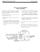
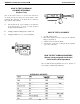
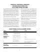
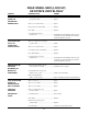
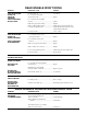
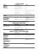
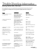
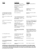
Table Of Contents
- 9020-7317 534B SERVICE MANUAL
- OPERATOR INSTRUCTIONS & LUBRICATION
- 8496 Operation & Lubrication Manual
- 8366 Operation & Lubrication Manual
- IMPORTANT SAFETY NOTICE
- INTRODUCTION
- SAFETY HIGHLIGHTS
- OPERATOR'S CAB
- CONTROL & INSTRUMENT IDENTIFICATION
- CHECKS & SERVICES BEFORE STARTING ENGINE
- ENGINE OPERATION
- WARM UP & OPERATIONAL CHECKS
- BRAKE SYSTEM
- STEERING SYSTEM
- DRIVE TRAIN
- MATERIAL HANDLING
- OPERATING PROCEDURES & TECHNIQUES
- PARKING
- STORAGE
- LUBRICATION & MAINTENANCE DIAGRAM
- 28327 Preventive Maintenance Chart
- HYDRAULIC SYSTEM
- 8497 System Operation Manual
- COVER
- NOMENCLATURE
- CAB CONTROLS AND GAGES
- ENGINE
- MAIN FRAME
- FRONT DRIVE AXLE
- DRIVE SHAFT
- REAR DRIVE AND STEERING AXLE
- TIRES
- TRANSMISSION & TORQUE CONVERTER
- STEERING CIRCUIT
- HYDRAULIC SERVICE BRAKE
- MECHANICAL PARKING BRAKE
- HYDRAULIC SYSTEM
- HYDRAULIC RESERVOIR
- HYDRAULIC PUMP
- MAIN CONTROL VALVE BANK
- MAIN PUMP CIRCUIT
- PILOT PUMP CIRCUIT
- HYDRAULIC CYLINDERS
- SWAY CIRCUIT
- LIFT CIRCUIT
- FRONT & REAR WHEEL DRIVE
- FORWARD / REVERSE LEVER (Neutral)
- FORWARD / REVERSE LEVER (Activated)
- INCHING
- TILT & COMPENSATING CIRCUITS
- OIL COOLER CIRCUIT
- CROWD (Boom In-Out) CIRCUIT
- AUXILIARY HYDRAULIC SYSTEM
- BOOM SECTIONS
- BOOM SLIDER PADS
- BOOM CROWD (IN-OUT) MOVEMENT
- MANUAL "QUICK-SWITCH" ASSEMBLY
- ELECTRICAL
- FUEL TANK
- 8369 System Operation Manual
- COVER
- NOMENCLATURE
- CAB CONTROLS AND GAGES
- ENGINE
- MAIN FRAME
- FRONT DRIVE AXLE
- DRIVE SHAFT
- REAR DRIVE AND STEERING AXLE
- TIRES
- TRANSMISSION & TORQUE CONVERTER
- STEERING CIRCUIT
- HYDRAULIC SERVICE BRAKES
- MECHANICAL PARKING BRAKE
- HYDRAULIC SYSTEM
- HYDRAULIC RESERVOIR
- HYDRAULIC PUMPS
- MAIN CONTROL VALVE BANK
- MAIN PUMP CIRCUITS
- PILOT PUMP CIRCUIT
- HYDRAULIC CYLINDERS
- SWAY CIRCUIT
- LIFT CIRCUIT
- FRONT & REAR WHEEL DRIVE
- FORWARD / REVERSE LEVER (Neutral)
- FORWARD / REVERSE LEVER (Activated)
- INCHING
- TILT & COMPENSATING CIRCUITS
- OIL COOLER CIRCUIT
- CROWD (Boom In-Out) CIRCUITS
- AUXILIARY HYDRAULIC SYSTEM
- BOOM SECTIONS
- BOOM SLIDER PADS
- BOOM CROWD (IN-OUT) MOVEMENT
- MANUAL "QUICK-SWITCH" ASSEMBLY
- ELECTRICAL
- FUEL TANK
- 81-515-009 Mico Sliding Caliper Disc Brakes Service Manual
- 81-600-001 Mico Guidelines for Installing Hydraulic Brake Components
- 81-950-016 Mico Brake Service Procedures
- 81-460-159 Mico Hydraulic Brake Valve
- 8497 System Operation Manual
- TESTING & ADJUSTING
- TROUBLE SHOOTING
- TRANSMISSION & TORQUE CONVERTER
- SM HR 182-3 Clark 18000 Series Powershift Transmission
- HOW THE UNITS OPERATE
- SECTIONAL VIEWS AND PARTS IDENTIFICATION
- DISASSEMBLY OF TRANSMISSION
- CLUTCH DISASSEMBLY
- CLEANING AND INSPECTION
- REASSEMBLY OF TRANSMISSION
- SERVICING MACHINE AFTER TRANSMISSION OVERHAUL
- TOWING OR PUSH STARTING
- SPECIFICATIONS AND SERVICE DATA
- LUBRICATION
- TROUBLESHOOTING GUIDE
- TYPICAL TWO AND THREE SPEED POWER FLOW
- PRESSURE CHECK POINTS
- CLUTCH AND GEAR ARRANGEMENT
- DRIVE PLATE INSTALLATION
- TRANSMISSION TO ENGINE INSTALLATION PROCEDURE
- SPEED SENSOR BUSHING INSTALLATION
- SM HR 182-3 Clark 18000 Series Powershift Transmission
- MISCELLANEOUS
- OPERATOR INSTRUCTIONS & LUBRICATION

The Gradall Material Handlers, Models 544 and
534B have unique 4 wheel drive systems. The drive is
a design between independent mechanical front drive
and hydraulic rear drive systems, accomplished
through an electric interface. This guide covers the
hydraulic drive system and the electric interface
between it and the mechanical drive. (Trouble shoot-
ing the mechanical drive proper is not covered.) In
order to trouble shoot one must have basic tools and a
basic understanding of how the drive works:
The front wheels are driven through a powershift
transmission. This transmission is the “master” drive
system. By “master” we mean the hydraulic rear
drive senses what the mechanical drive is doing and
reacts accordingly. The rear drive signal for forward
and reverse is obtained from two microswitches
located under the dash near the transmission control
cable. This signal ultimately drives the spool of the
forward/reverse valve. The sigual for first gear for
the rear drive comes from a pressure switch connected
to the first gear clutch port on the transmission.
Likewise, the second gear signal originates at the
second gear clutch port. Both of these signals control
the series/parallel valve spool, i.e., parallel flow in
first, series flow in second. During third gear opera-
tion the rear drive automatically free wheels, this
means that in third the machine is two wheel drive
which yields a fuel efficient system during long high
speed runs. This free-wheel signal comes from the
third gear transmission clutch pressure port. The
free-wheeling signal actuates the cavitation valve.
NOTE: When roading over two (2) miles the rear
hubs shouid be disengaged.
Inching is accomplished by disconnecting the me-
chanical front wheel drive and powering only with
the rear wheels. When depressing the clutch/brake
pedal, an electrical signal is sent disconnecting the
front drive transmission, further movement of the
clutch/brake pedal varies the flow to the rear drive
through the utilization of the hydraulic controller.
GRADALL
®
MATERIAL HANDLER
TROUBLE SHOOTING FOR
544 & 534B DRIVE SYSTEM
REAR WHEELS DRAG ENGINE DOWN
PROBLEM PROBABLE CAUSE REMEDY
CAVITATION Loose wire at cavitation valve
VALVE NOT or third gear pressure switch............................ Repair
OPERATIONAL
Too much back pressure in pilot
SERIES PARALLEL drainline at series/parallel valve.............................Repair
SHIFTED IN
THIRD GEAR Faulty third gear pressure switch ....................... Replace
Faulty cavitation valve...........................................Check wiring from pressure switch. eck valve.
Faulty series/parallel valve
(broken springs, sticky spool)............................... Check solenoids and wiring. Clean spool.
Replace spring, O-Rings.
CONTROLLER Controller stuck ................................................... Check valve and wiring
ONLY PARTLY
SHIFTED IN FIRST Low pilot pressure ................................................Reset pilot pressure, 350 psi
& SECOND GEAR
Form No. 8360r
1