® ® SERVICE MANUAL ® 534B 9020-7317 July 2002 Starting S/N 8244001 thru 8744109 CORPORATE OFFICE GRADALL DIVISION JLG INDUSTRIES, INC. 1 JLG DRIVE McConnellsburg, PA 17233-9533 USA Telephone: (717) 485-5161 Fax: (717) 485-6417 JLG INDUSTRIES, INC. 406 Mill Avenue S.W.
® ® OPERATION & LUBRICATION MANUAL ® 534 9103-1148 July 2002 Starting S/N 8444490 Also Covers S/N 8444474 Form #8496 Original Issue 12/84 CORPORATE OFFICE GRADALL DIVISION JLG INDUSTRIES, INC. 1 JLG DRIVE McConnellsburg, PA 17233-9533 USA Telephone: (717) 485-5161 Fax: (717) 485-6417 JLG INDUSTRIES, INC. 406 Mill Avenue S.W.
IMPORTANT SAFETY NOTICE Safe operation depends on reliable equipment and proper operating procedures. Performing the checks and services described in this manual will help to keep your Gradall Materials Handler in reliable condition and use of the recommended operating procedures can help you avoid accidents. Because some procedures may be new to even the experienced operator we recommend that this manual be read, understood and followed by all who operate the unit.
3
SAFETY HIGHLIGHTS Read and understand this manual, the Gradall Loed/Materials Handler Safety Manual and all instructional decals and plates before starting, operating or performing maintenance procedures on this equipment. Operators of this equipment must have successfully, completed a training program in the safe operation of this type of material handling equipment. Most safety notes included in this manual involve characteristics of the Model 534B Loed/Materials Handler.
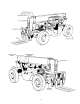
OPERATOR’S CAB The standard cab is open on three sides and includes an overhead guard to provide protection from falling objects. Never operate the handler unless the overhead guard is in place and in good condition. A fully enclosed cab with Plexiglass windows and a lockable door is available as an option. The cab door can be secured in the fully opened or closed position. Be sure the door is fully secured when operating the handler.
CHECKS AND SERVICES BEFORE STARTING ENGINE (To be performed at beginning of each work shift) enter these ports, it can shorten the life of o-rings. seals, packings and bearings. Use extreme caution when checking items beyond your normal reach. Use an approved safety ladder. When adding fluids or changing filter elements, refer to the lubrication section of this manual to determine the proper type to be used. Before removing filler caps or fill plugs, wipe all dirt and grease away from the ports.
ENGINE OPERATION NOTE: If engine is being started at beginning of work shift be sure to perform all “ CHECKS AND SERVICES BEFORE STARTING ENGINE” (Page 6). Starting Engine installed ether starting aid, fully raise and depress starting aid knob one time only before cranking engine. If you use a different starting aid, be sure to follow manufacturer’s instructions carefully. Excessive ether may damage engine. 1.
Stopping the Engine Operate engine at idle speed for a few minutes before turning it off. This allows engine coolant and lubricating oil to carry excessive heat away from critical engine areas. cylinder walls and dilute lubricant in crankcase. To stop engine, allow engine to run at idle for a few minutes and then turn key counterclockwise to stop position. Be sure to remove key from ignition switch before leaving cab.
BRAKE SYSTEM Service Brakes General The brake system furnished on The handler includes a service brake, parking brake and Mico lock. The power-assisted hydraulic service brake is applied only to front wheels of handler. Because service braking and “inching” (slow travel) functions overlap, some features of inching will be discussed here. Refer to Drive Train Section for additional information on inching travel.
To release parking brake, push parking brake lever forward (to horizontal position). Parking Brakes The parking brake locks the front axle by means of a cable actuated brake caliper acting on a brake disc attached to the axle input yoke. Always apply parking brake before leaving cab. Neither leaving the unit in gear nor applying the Mico Lock will prevent unit from rolling. Refer to page 17 for parking procedure. Parking brake tension can be increased by turning knob at end of lever clockwise.
DRIVE TRAIN General Transmission The drive train provides two and four wheel drive and includes the engine, torque converter, transmission, propel shaft and front and rear driving axles. The transmission provides three speed ranges for both forward and reverse travel. Inching travel is directly related to drive train functions and will be discussed in this section. Gear mph 1st 2.8 2nd 6.0 3rd 15.9 3rd* 17.9 kmph 4.5 9.6 25.6 28.
Rear Driving Axle travel functions only in first and second gears. There is no hydraulic flow to drive motors in third gear. The rear driving axle includes planetary hubs which are powered by hydraulic motors mounted on the inner face of the hubs. Hydraulic flow to drive motors is provided only in first and second gear speed ranges. Drive motors are free-floating in third gear. Inching travel is controlled by the service brake/inching travel pedal.
MATERIAL HANDLING Leveling To Level Handler: Position machine in best location to lift or place 1. load and apply brake. The handler is designed to permit tilting main frame eight degrees to left or right to compensate for uneven ground conditions. Raising the boom (loaded or unloaded) when handler is leaning to the side can cause machine to tip over with little or no warning. 2. Observe level indicator to determine whether machine must be leveled. Note position of indicator for later realignment. 3.
Attachments A serial number plate is attached to all attachments and indicates maximum capacity for that attachment. However, the capacity shown on this plate may be incorrect in relation to your machine. Although the carriage/fork combination is most frequently used, a number of other attachments are available for use with the handler. can be provided for light duty work. A truss boom is available to extend maximum reach and height and can be fitted with a winch when required.
OPERATING PROCEDURES & TECHNIQUES This section highlights some common procedures and discusses areas which may be new to even the experienced operator. With boom raised above horizontal, forks can be removed from a load by moving boom control lever back and to the left until forks move rearward horizontally. Hydraulic Controls With boom lowered below horizontal, forks can be inserted under a load by moving boom control lever back and to the right until forks move forward horizontally.
Rated Capacity Chart Boom Extension Numbers across bottom of chart (0' to 22') and numbers parallel to boom (2' to 18') represent boom extension as measured from fully retracted position to extended position. These numbers do not reflect total boom length, only the number of feet of extension from fully retracted position. Number decals on boom section number two (4, 8 12, 16 and 20) relate directly to boom extension. The largest number which can be read from operator’s seat indicates total boom extension.
based on hydraulic limitations, the maximum load may be handled anywhere within reach of machine. Never use “tipping” method to determine safe lifting capacity. This could cause the load to fall or the machine to tip over. Truss Boom/Winch Capacity Lift capacity for a truss boom or a truss boom/winch combination. If furnished with the handler, is shown on the Attachment Capacity plate.
LUBRICATION & MAINTENANCE DIAGRAM Lubricate Notes • Lubricate points indicated by dotted leaders on both sides of unit. • Intervals shown are for normal (8 hour day) usage and conditions. Adjust intervals for abnormal usage and conditions. • • • Clean lubrication fittings before lubricating. • Clean filter and air cleaner housing using diesel fuel. Dry components thoroughly using a lint free cloth. 20). • Check lubricant levels when lubricant is cool.
Daily or Every 10 Hours Lube Symbol No. of Points 1. Carriage Tilt Cylinder Pivots CG 2 2. Boom Extension Cable Sheave CG 1 3. Boom Slide Bearings (extend boom fully and coat all wear paths on boom sections 2 and 3 - retract and extend boom fully three times and wipe excess grease from bearings) CG 5. Boom Hoist Cylinder Pivots CG 7. Boom Retraction Cable Sheave CG 1 Front Boom Slide Bearings (check retaining bolt torque - 12 13. Front Hub Drain Plugs (dram and refill) GO 2 15.
Recommended Lubricants & Capacities Application Symbol When Used Grade Specifications Capacities** English Liters Engine Crankcase EO (engine oil) All year 10W-30 - 12 quarts 7.8 Engine Cooling System 50% water/50% anti-freeze All year Permanent - 24 quarts 22.7 Transmission ATF (automatic trans. fluid) All year - 20 quarts 18.9 40gallons 151.4 Fuel Tank DF (diesel fuel) All year #2 ATF-FM DEXRON A.S.L.E. No. H-215* Hydraulic System HF (Hydraulic fluid) All year - A.P.I.
HAND SIGNALS Standard Signals - When handler work conditions require hand signals, they shall be provided or posted conspicuously for the use of both signalman and operator. No handler motions shall be made unless signals are clearly understood by both signalman and operator. Special Signals - When signals for auxiliary equipment functions or conditions not covered are required, they shall be agreed upon in advance by the operator and signalman.
® ® OPERATION & LUBRICATION MANUAL ® 534 9100-3023 July 2002 Starting S/N 8244001L Form #8366 Original Issue 12/83 CORPORATE OFFICE GRADALL DIVISION JLG INDUSTRIES, INC. 1 JLG DRIVE McConnellsburg, PA 17233-9533 USA Telephone: (717) 485-5161 Fax: (717) 485-6417 JLG INDUSTRIES, INC. 406 Mill Avenue S.W.
3
SAFETY HIGHLIGHTS Read and understand this manual, the Gradall Loed/ Materials Handler Safety Manual and all instructional decals and plates before starting, operating or performing maintenance procedures on this equipment. Operators of this equipment must have successfull completed a training program in the safe operation of this type of material handling equipment. Most safety notes included in this manual involve characteristics of the Model 534B Loed/Materials Handler.
OPERATOR’S CAB The standard cab is open on three sides and includes an overhead guard to provide protection from falling objects. variations in operator size. The adjustment release/lock lever is located beneath front edge of seat. Wear seat belt at all times. An optional windshield wiper is available for use with enclosed cabs. An ON/OFF control switch is located on the wiper motor. Never operate the handler unless the overhead guard is in place and in good condition.
CHECKS AND SERVICES B E F O R E S TA R T I N G E N G I N E (To be performed at beginning of each work shift) enter these ports, it can shorten the life of o-rings seals, packings and bearings. Use extreme caution when checking items beyond your normal reach. Use an approved safety ladder. When adding fluids or changing filter elements refer to the lubrication section of this manual to determine the proper type to be used.
ENGINE OPERATION NOTE: If engine is being started at beginning of work shift be sure to perform all “CHECKS AND SERVICES BEFORE STARTING ENGINE” (page 6). Starting Engine installed ether starting aid, fully raise and depress starting aid knob one time only before cranking engine. If you use a different starting aid, be sure to follow manufacturer’s instructions carefully. Excessive ether may damage engine. 1.
Stopping the Engine cylinder walls and dilute lubricant in crankcase. Operate engine at idle speed for a few minutes before turning it off. This allows engine coolant and lubricating oil to carry excessive heat away from critical engine areas. To stop engine, allow engine to run at idle for a few minute and then turn key counterclockwise to stop position. Be sure to remove key from ignition switch before leaving cab.
BRAKE SYSTEM General Service Brakes The brake system furnished on the handler includes a service brake, parking brake and Mico lock. The power-assisted hydraulic service brake is applied only to front wheels of handler. Because service braking and “inching” (slow travel) functions overlap, some features of inching will be discussed here. Refer to Drive Train Section for additional information on inching travel.
3. Pull Mico Lock lever back to lock position (lever vertical) and then release brake pedal. To release parking brake, push parking brake lever forward (to horizontal position). To Release Mico Lock Parking brake tension can be increased by turning knob at end of lever clockwise. Release Mico Lock by pushing lever forward to release position (lever horizontal). Parking Brakes Always apply parking brake before leaving cab.
DRIVE TRAIN General Transmission The drive train provides two and four wheel drive and includes the engine, torque converter, transmission, propel shaft and front and rear driving axles. The transmission provides three speed ranges for both forward and reverse travel. Inching travel is directly related to drive train functions and will be discussed in this section.
Rear Driving Axle travel functions only in first and second gears. There is no hydraulic flow to drive motors in third gear. The rear driving axle includes planetary hubs which are powered by hydraulic motors mounted on the inner face of the hubs. Hydraulic flow to drive motors is provided only in first and second gear speed ranges. Drive motors are free-floating in third gear. Inching travel is controlled by the service brake/inching travel pedal. This pedal has three separate functions: 1.
MATERIAL HANDLING Leveling To Level Handler: The handler is designed to permit tilting main frame eight degrees to left or right to compensate for uneven ground conditions. 1. Position machine in best location to lift or place load and apply brake. 2. Observe level indicator to determine whether machine must be leveled. Note position of indicator for later realignment. Raising the boom (loaded or unloaded) when handler is leaning to the side can cause machine to tip over with little or no warning. 3.
Attachments A serial number plate is attached to all attachments and indicates maximum capacity for that attachment. However, the capacity shown on this plate may be incorrect In relation to your machine. Although the carriage/fork combination is most frequently used, a number of other attachments are available for use with the handler. A material bucket can be provided for light duty work. A truss boom is available to extend maximum reach and height and can be fitted with a winch when required.
O P E R AT I N G P R O C E D U R E S & T E C H N I Q U E S With boom raised above horizontal, forks can be remove from a load by moving boom control level back and to the left until forks move rearward horizontally. This section highlights some common procedures and discusses areas which may be new to even the experienced operator.
Rated Capacity Chart Boom Extension Numbers across bottom of chart (0 22') and numbers parallel to boom (2’to 18') represent boom extension as measured from fully retracted position to extended position. These numbers do not reflect total boom length, only the number of feet of extension from fully retracted position. Number decals on boom section number two (4, 8, 12, 16 and 20) relate directly to boom extension. The largest number which can be read from operator’s seat indicates total boom extension.
based on hydraulic limitations, the maximum load may be handled anywhere within reach of machine. Never use “tipping” method to determine safe lifting capacity. This could cause the load to fall or the machine to tip over. Truss Boom/Winch Capacity Lift capacity for a truss boom or a truss boom, winch combination, if furnished with the handler, is shown on the Attachment Capacity plate.
LUBRICATION & MAINTENANCE DIAGRAM Lubrication Notes l Lubricate points indicated by dotted leaders on both sides of unit. l Clean lubrication fittings before lubricating. l Intervals shown are for normal (8 hour day) l Clean filter and air cleaner housing using diesel fuel. Dry components thoroughly using a lint free cloth. l Check lubricant levels when lubricant is cool. l Drain engine and gear operation when lubricant is hot. usage and conditions. Adjust abnormal usage and conditions.
Daily or Every 10 Hours Lube No. of Symbol Points 2 1. Carriage Tilt Cylinder Pivots CG 1 2. Boom Extension Cable Sheave CG 3. Boom Slide Bearings (extend boom fully and coat all wear paths on boom sections 2 and 3-retract and extend boom fully three times and wipe excess grease from bearings) 8 5. Boom Hoist Cylinder Pivots CG 2 7. Boom Retraction Cable Sheave CG 1 8. Boom Pivot CG 1 9. Compensating Cylinder Pivots CG 2 10. Boom Head/Carriage Pivot CG 2 14. Carriage Tilt/Machine Level Lever Pivot CG 16.
Recommended Lubricants & Capacities *Specific hydraulic fluid specifications are shown below. **Capacities are approximate - check level to be sure. Hydraulic Fluid Specifications: Grade, ASTM Grade, AGMA Gravity, ° API Color, ASTM Flash Point COC, ° F Fire Point, COC. ° F Pour Point, ° F 215 1 31.0 2.0 440 490 -30 Viscosity: SUS at 100°F SUS at 210°F Viscosity Index Aniline Point, °F Foam Test, ASTM Neutralization Number 215 48.0 105 222 Pass 1.4 Carbon Residue, Rams. wt 0.4 Zinc, wt% 0.
FORM NO. HE 28327 NOTE: See Service Manual For Complete Details FUEL TANK: Fill Daily 40 gal. #2 Diesel RADIATOR: Check Level Daily 3 gal. Water-3 gal. Anti-freeze REAR AXLE LINKAGE: Grease Daily (15) REAR AXLE PIVOT: Grease Daily CYLINDERS: Grease Daily (14) MPEP Contains Moly N LG 1 No. 2 BOOM TRUNION PIN: Grease Daily (1) FUEL FILTER: Change - Three Months HYDRAULIC RESERVOIR: TIRES: Check Pressure Weekly Check Level Daily 55 psi.
GRADALL LOED MATERIAL HANDLER 534B SYSTEM OPERATION NOMENCLATURE 18. Main Valve Bank (Under Cab) 19. Operator’s Cab 20. Operator’s Controls 21. Transmission Filter 22. Transmission & Torque Converter 23. Drive Shaft 24. Parking Brake Assembly 25. Pilot Relief Valve 26. Compensating Cylinder 27. Crowd Cylinder 28. Three Section Boom 29. Tilt Cylinder 30. Carriage 31. Manual “Quick-Switch” 32. Forks 33. Lift Cylinders (2) 34. Brake Master Cylinder 1. Front Axle Pivot 2. Front Planetary Axle 3.
GRADALL LOED MATERIAL HANDLER 534B SYSTEM OPERATION CAB CONTROLS & GAGES 14. FUEL GAGE 15. TEMPERATURE GAGE 16. OIL PRESSURE GAGE 17. HEATER FAN SWITCH (Option) 18. LIGHT SWITCH (Option) 19. HORN BUTTON 20. ROTATING BEACON SWITCH (Option) 21. IGNITION KEY 22. ETHER START KNOB (Option) 23. STARTER BUTTON 24. STEERING WHEEL 25. HOUR METER 26. BRAKE WARNING LIGHT (Low Pressure) 1. CARRIAGE TILT & SWAY CONTROL LEVER 2. FORWARD-REVERSE LEVER 3. LEVEL INDICATOR 4. TRANSMISSION SPEED SELECTOR LEVER 5.
GRADALL LOED MATERIAL HANDLER 534B SYSTEM OPERATION ENGINE To supply power for the front wheel drive and for the various hydraulic circuits’a diesel engine is used. It runs at 900 rpm low idle. Depressing the accelerator pedal all the way, the engine will run 2800 rpm. With a nominal load the engine will average out at 2600 rpm and will produce 102 gross BHP. The engine speed governs both over-the-road travel speed and the hydraulic circuit speeds.
GRADALL LOED MATERIAL HANDLER 534B SYSTEM OPERATION MAIN FRAME REAR DRIVE AND STEERING AXLE The 534B has an all welded main frame with 1032 pounds of counterweight on rear for stability. The rear axle assembly pivots up and down on the main frame. Each wheel is powered by a hydraulic motor, driving through a planetary hub. Two steering cylinders are used to turn the wheels. At maximum turn radius, the outside wheel turns about 90° to the pivoting axle. The inside wheel turns about 87°.
GRADALL LOEB MATERIAL HANDLER 534B SYSTEM OPERATION TRANSMISSION AND TORQUE CONVERTER The tranmission - torque converter combination has neutral starting, shifting without stopping, 3 speeds forward and 3 speeds in reverse. Gear selection lever is on the right side of the steering column. The neutral, forward or reverse lever is on the left side. When the brake foot pedal is pressed down, either for braking or inching, the transmission de-clutches and no power goes to the front axle.
GRADALL LOED MATERlAL HANDLER 534B SYSTEM OPERATION HYDRAULIC SERVICE BRAKES To actuate the service brakes, two different circuits are used. One uses system hydraulic oil. and the other uses brake fluid. The hydraulic oil circuit consists of the pilot pump (A), and the pilot relief valve (B), and a booster brake valve (C).
GRADALL LOED MATERIAL HANDLER 534B SYSTEM OPERATION HYDRAULIC SYSTEM ABCDEFGHJKLMNOPQ- RST- TILT CYLINDER RESERVOIR FILTER HYDRAULIC OIL RESERVOIR LOW TORQUE INCHING SOLENOID VALVE PILOT PUMP PILOT RELIEF VALVE (450 psi) CROWD CYLINDER HOIST (Lift) CYLINDERS (2) COMPENSATING CYLINDER PARALLEL SOLENOID VALVE SERIES SOLENOID VALVE SERIES/PARALLEL VALVE STEERING CYLINDERS (2) REAR HYDRAULIC DRIVE MOTORS FWD/REV PILOT PRESSURE CONTROL VALVE FWD/REV VALVE UVWXYZAABBCCDD- 8 CAVITATION SOLENOID VALVE MAIN
GRADALL LOED MATERIAL HANDLER 534B SYSTEM OPERATION HYDRAULIC RESERVOIR The reservoir is located on the right side of the machine, directly in front of the fuel tank. It holds 24 gallons of hydraulic oil. The system holds 40 gallons. The measuring dip stick is a part ot the filler cap. In the filler opening is a wire screen. Oil returning to the reservoir passes thru a 10 micron replaceable type filter. As oil is drawn off by the pumps, it passes thru a 100 mesh screen.
GRADALL LOED MATERIAL HANDLER 534B SYSTEM OPERATION MAIN PUMP CIRCUITS The two section main tandem pump supplies oil for two separate circuits. Oil from the base section supplies oil through a Priority Valve (to assure a supply of oil for steering) and also routed to Fwd/Rev Control Valve. Oil from the end section is routed to the main control valve. Both circuits have 3000 psi relief valves. The rear drive pump relief valve is located inside the frame on the left side.
GRADALL LOED MATERIAL HANDLER 534B SYSTEM OPERATION HYDRAULIC CYLINDERS There are eight hydraulic cylinders: Sway, Lift (2), Compensating, Tilt, Crowd (Boom In-Out), and Rear Wheel Steering (2). On the Tilt, Crowd and Lift Cylinders, a counterbalance valve is used to protect against broken hoses and to control lowering actions. The Sway Cylinder has two piloted check valves to provide a positive lock of oil in the cylinder.
GRADALL LOED MATERIAL HANDLER 534B SYSTEM OPERATION SWAY CIRCUIT The sway circuit permits the operator to level the main frame of the machine in relation to the position of the front axle. With the sway cylinder the operator can tilt the frame up to 8° in either direction from horizontal. Movement of the sway lever to the right or left actuates a plunger in the first control valve section, and oil is routed to the sway cylinder, and the machine sways right or left.
GRADALL LOED MATERIAL HANDLER 534B SYSTEM OPERATlON FRONT & REAR WHEEL DRIVE The oil supply to the rear drive motors will vary depending on the position of the gear selection lever. The purpose of this is to coordinate the speed of the rear wheels with the speed of the front wheels. The 534B hasaconventional front wheeldrive, with power from the engine. It has a torque converter and transmission with a drive shaft and differential, and a pair of planetary wheel ends.
GRADALL LOED MATERIAL HANDLER 534B SYSTEM OPERATION FORWARD/REVERSE LEVER (Neutral) When Forward/Reverse Lever is in neutral position, electrical contacts are not made at the Fwd/Rev Switches (J) and the oil flow in the circuit is as follows: Oil from reservoir (A) is drawn into the main pump section (B). It then flows to the priority valve (D) where a portion is available for the steering circuit. First, the oil is exposed to the circuit main relief valve (C) which is set at 3000 psi.
GRADALL LOED MATERIAL HANDLER 534B SYSTEM OPERATION INCHING control pressure to bleed off to tank, thereby metering the Forward/Reverse valve to neutral. The inching feature allows the operator, when carrying a load, to move the handler very slowly for maneuvering in tight places. As the operator continues to depress the brakeinching pedal (A) and the inching valve (C) rotates, the pressure controlling the Fwd/Rev Valve varies.
GRADALL LOED MATERIAL HANDLER 534B SYSTEM OPERATION TILT & COMPENSATING CIRCUITS Both cylinders are of identical size so that as the boom angle changes, a like volume of oil is transferred to or from the tilt cylinder, keeping the fork level or in the same position. The tilt circuit raises or lowers the angle of the fork or other attachment a total of 114°.
GRADALL LOED MATERIAL HANDLER 534B SYSTEM OPERATION CROWD (Boom In-Out) CIRCUIT The crowd circuit allows the operator to extend and retract the boom sections a total of 18 feet. Nine foot extension is obtained from the movement of a hydraulic cylinder joined to the first section and the second section. Movement of the 2nd section and a combination of cables and sheaves moves the 3rd section.
GRADALL LOED MATERIAL HANDLER 534B SYSTEM OPERATION BOOM SECTIONS BOOM SLIDER PADS The boom sections move in and out on slide wear pads. These pads are positioned on the top bottom and sides of the boom to protect the boom frame against excessive wear.
GRADALL LOED MATERIAL HANDLER 534B SYSTEM OPERATION BOOM CROWD (IN-OUT) MOVEMENT When the control lever for the crowd action is activated, the 2nd and 3rd boom sections move in and out equally. Two cables are used. The top one is bolted to the rear of the main boom and runs forward around the push beam front sheave and back to the anchor point at the bottom rear of the 3rd boom section.
GRADALL LOED MATERlAL HANDLER 534B SYSTEM OPERATION ELECTRICAL The electrical circuit consists of a 12 volt, 55 amp. alternator, two batteries, each rated at 565 Cold Cranking amps at 0ø F, and 12 volt gages. Use the electrical schematic for trouble shooting the circuit. FUEL TANK A 40 gallon fuel tank is mounted to the frame on the right hand side of the machine. It includes a wire mesh strainer at the fill cap a suction screen and a sending unit to the cab fuel gage.
GRADALL LOED MATERIALS HANDLER 534B SYSTEM OPERATION NOMENCLATURE 1. 2. 3. 4. 5. 6. 7. 8. 9. 10. 11. 12. 13. 14. 15. 16. 17. 18. 19. 20. 21. 22. 23. 24. 25. 26. 27. 28. 29. 30. 31. 32. 33.
GRADALL LOED MATERIALS HANDLER 534B SYSTEM OPERATION CAB CONTROLS & GAGES 1. 2. 3. 4. 5. 6. 7. 8. 9. 10. 11. 12. 13. CARRIAGE TILT & SWAY CONTROL LEVER FORWARD-REVERSE LEVER LEVEL INDICATOR TRANSMISSION SPEED SELECTOR LEVER BOOM CONTROL (Up-Down - In-Out) AUXILIARY CONTROL LEVER (Option) PARKING BRAKE LEVER ACCELERATOR PEDAL BRAKE-INCHING PEDAL SEAT POSITION CONTROLS MICO BRAKE LOCK LEVER TRANSMISSION TEMPERATURE GAGE AMMETER GAGE 14. 15. 16. 17. 18. 19. 20. 21. 22. 23. 24. 25. 26.
GRADALL LOED MATERIALS HANDLER 534B SYSTEM OPERATION ENGINE To supply power for the front wheel drive and for the various hydraulic circuits, a diesel engine is used. It runs at 900 rpm low idle. Depressing the accelerator pedal all the way, the engine will run 2800 rpm. With a nominal load the engine will average out at 2600 rpm and will produce 90 gross BHP. The engine speed governs both over-the-road travel speed and the hydraulic circuit speeds.
GRADALL LOED MATERIALS HANDLER 534B SYSTEM OPERATION MAIN FRAME REAR DRIVE AND STEERING AXLE The 534B has an all welded main frame with 850 pounds of counterweight on rear for stability. The rear axle assembly pivots up and down on the main frame. Each wheel is powered by a hydraulic motor, driving through a planetary hub. Two steering cylinders are used to turn the wheels. At maximum turn radius, the outside wheel turns about 90° to the pivoting axle. The inside wheel turns about 87°.
GRADALL LOED MATERIALS HANDLER 534B SYSTEM OPERATION TRANSMISSION AND TORQUE CONVERTER The transmission-torque converter combination has neutral starting, shifting without stopping, 3 speeds forward and 3 speeds in reverse. Gear selection lever is on the right side of the steering column. The neutral, forward or reverse lever is on the left side. When the brake foot pedal is pressed down, either for braking or inching, the transmission de-clutches and no power goes to the front axle.
GRADALL LOED MATERIALS HANDLER 534B SYSTEM OPERATION HYDRAULIC SERVICE BRAKES To actuate the service brakes, two different circuits are used. One uses system hydraulic oil, and the other uses brake fluid. The hydraulic oil circuit consists of the pilot pump (A), the pilot relief valve (B). a one-way check valve (C), which prevents any back-up of oil. A pressure switch sender (D) to activate the dash light, an accumulator (E) which contains a nitrogen precharge, and a booster brake valve (F).
GRADALL LOED MATERIALS HANDLER 534B SYSTEM OPERATION HYDRAULIC SYSTEM View of Panel (Rear of Cab) A- TILT CYLINDER B- RESERVOIR FILTER C- HYDRAULIC OIL RESERVOIR D- LOW TORQUE INCHING SOLENOID VALVE E- PILOT PUMP F- PILOT RELIEF VALVE 500 psi G- CROWD CYLINDER H- HOIST (Lift) CYLINDERS (2) J- COMPENSATING CYLINDER K- PARALLEL SOLENOID VALVE L- SERIES SOLENOID VALVE M -SERIES/PARALLEL VALVE N- STEERING CYLINDERS (2) O- REAR HYDRAULIC DRIVE MOTORS P- FWD/REV PILOT PRESSURE CONTROL VALVE Q- FWD/REV VALVE
GRADALL LOED MATERIALS HANDLER 534B SYSTEM OPERATION HYDRAULIC RESERVOIR The reservoir is located on the right side of the machine. directly in front of the fuel tank. It holds 24 gallons of hydraulic oil. The system holds 40 gallons. The measuring dip stick is a part of the filler cap. In the filler opening is a wire screen. Oil returning to the reservoir passes thru a 10 micron replaceable type filter. As oil is drawn off by the pumps, it pasees thru a 100 mesh screen.
GRADALL LOED MATERIALS HANDLER 534B SYSTEM OPERATION MAIN PUMP CIRCUITS The two section main tandem pump supplies oil for two separate circuits. Oil from the base section supplies oil through a Priority Valve (to assure a supply of oil for steering) and also routed to Fwd/Rev Control Valve. Oil from the end section is routed to the main control valve. Both circuits have 3000 psi relief valves. The rear drive pump relief valve is located inside the frame on the left side.
GRADALL LOED MATERIALS HANDLER 534B SYSTEM OPERATION HYDRAULIC CYLINDERS There are eight hydraulic cylinders: Sway, Lift (2), Compensating, Tilt, Crowd (Boom In-Out), and Rear Wheel Steering (2). On the Tilt, Crowd and Lift Cylinders, a counterbalance valve is used to protect against broken hoses and to control lowering actions. The Sway Cylinder has two piloted check valves to provide a positive lock of oil in the cylinder.
GRADALL LOED MATERIALS HANDLER 534B SYSTEM OPERATION SWAY CIRCUIT The sway circuit permits the operator to level the main frame of the machine in relation to the position of the front axle. With the sway cylinder the operator can tilt the frame up to 8ø in either direction from horizontal. Movement of the sway lever to the right or left actuates a plunger in the first control valve section, and oil is routed to the sway cylinder, and the machine sways right or left.
GRADALL LOED MATERIALS HANDLER 534B SYSTEM OPERATION FRONT & REAR WHEEL DRIVE The oil supply to the rear drive motors will vary depending on the position of the gear selection lever. The purpose of this is to coordinate the speed of the rear wheels with the speed of the front wheels. The 534B has a conventional front wheel drive, with power from the engine. It has a torque converter and transmission with a drive shaft and differential, and a pair of planetary wheel ends.
GRADALL LOED MATERIALS HANDLER 534B SYSTEM OPERATION FORWARD/REVERSE LEVER (Neutral) When Forward/ Reverse Lever is in neutral position, electrical contacts are not made at the Fwd/ Rev Switches (J) and the oil flow in the circuit is as follows: Oil from reservoir (A) is drawn into the main pump section (B). It then flows to the priority valve (D) where a portion is available for the steering circuit. First, the oil is exposed to the circuit main relief valve (C) which is set at 3000 psi.
GRADALL LOED MATERIALS HANDLER 534B SYSTEM OPERATION INCHING As the operator continues to depress the brakeinching pedal (A) and the potentiometer (H) rotates, the electrical current controlling the Fwd/Rev Pilot Control Valve varies. The inching feature allows the operator, when carrying a load, to move the handler very slowly for maneuvering in tight places. To operate the inching feature, the operator depresses the brake-inching foot pedal (A) approximately 1/2" to 1".
GRADALL LOED MATERIALS HANDLER 534B SYSTEM OPERATION T I LT & C O M P E N S AT I N G C I R C U I T S Both cylinders are of a identical size so that as the boom angle changes, a like volume of oil is transfered to or from the tilt cylinder, keeping the fork level or in the same position. The tilt circuit raises or lowers the angle of the fork or other attachment a total of 114°.
GRADALL LOED MATERIALS HANDLER 534B SYSTEM OPERATION CROWD (Boom In-Out) CIRCUIT The crowd circuit allows the operator to extend and retract the boom sections a total of 18 feet. Nine foot extension is obtained from the movement of a hydraulic cylinder joined to the first section and the second section. Movement of the 2nd section and a combination of cables and sheaves moves the 3rd section.
GRADALL LOED MATERIALS HANDLER 534B SYSTEM OPERATION BOOM SECTIONS BOOM SLIDER PADS The boom sections move in and out on slide wear pads. These pads are positioned on the top, bottom and sides of the boom to protect the boom frame against excessive wear.
GRADALL LOED MATERIALS HANDLER 534B SYSTEM OPERATION BOOM CROWD (IN-OUT) MOVEMENT When the control lever for the crowd action is activated, the 2nd and 3rd boom sections move in and out equally. Two cables are used. The top one is bolted to the rear of the main boom and runs forward around the push beam front sheave and back to the anchor point at the bottom rear of the 3rd boom section.
GRADALL LOED MATERIALS HANDLER 534B SYSTEM OPERATION ELECTRICAL The electrical circuit consists of a 12 volt, 55 amp. alternator, two batteries, each rated at 565 Cold Cranking amps at 0ø F, and 12 volt gages. Use the electrical schematic for trouble shooting the circuit. A CM Assembly is located under the right hand dashboard which contains a voltage regulator, diodes, capacitors and a circuit breaker with a 5 amp manual re-set button.
General Guidelines for installing Hydraulic Brake Components MICO Hydraulic Brake Components are precision built devices and must be treated as such. The following guidelines must be followed at the time of installation to ensure optimum performance. Where to Mount To properly locate the brake component or brake line, you must. . . 1. Make it convenient for operator. 2. Use the shortest and most protected route. Protect components from road salts and general debris. 3.
Burnishing Procedures for MICO Caliper Disc Brakes TECHNICAL NOTICE Maximum torque will be achieved only after the brake has been properly burnished. Actual customer testing will be required to determine final acceptance and approval of brake system components. MICO recommends the following SAE burnishing procedures be performed immediately following the installation and adjustment of the brake. These “SAE recommended practices” (J360; paragraph 7.3 for parking brakes and J786a; paragraph 5.
Recommended Brake Service Procedures to Reduce Exposure to Non-Asbestos Fiber TECHNICAL NOTICE FOR ALL MICO NON-ASBESTOS BRAKE LININGS Recently manufactured brake linings no longer contain asbestos fibers. In place of asbestos, these linings contain a variety of ingredients, including glass fibers, mineral wool, aramid fibers, ceramic fibers, and carbon fibers. At present, OSHA does not specifically regulate these non-asbestos fibers, except as nuisance dust.
Service Instructions HYDRAULIC BRAKE VALVE Master Cylinder Section REPAIR KIT 02-400-184 MASTER CYLINDER SECTION - Automotive Brake Fluid POWER ASSIST SECTION - Mineral Base Hydraulic Oil FIGURE 1 This instruction sheet services the Master Cylinder Section for these model numbers: 02-460-272 02-460-392 02-460-402 TYPICAL SYSTEM SCHEMATIC MICO Broke Valve (This circuit may not apply to your installation) Brokes FIGURE 2 Power Steering Cylinder Reservoir
REMOVING BRAKE VALVE FROM VEHICLE AND SEPARATING SECTIONS (Refer to Figures 1 & 3) 1. Remove Brake Valve from vehicle by disconnecting necessary fluid lines, disconnecting push rod and removing mounting bolts. Drain fluid from assembly. 2. Separate Master Cylinder Section from Power Assist Section by removing three cap screws and three lock washers.
l Items included in Repair Kit 02-400-184 * Not used on all models FIGURE 4
BLEEDING PROCEDURES NOTE Use only proper fluid specified by vehicle manufacturer. Never reuse fluid that has been drained from the system. Be sure that you maintain a high level of fluid in the reservoir during and after the entire bleeding process. PRESSURE BLEEDING INSTRUCTIONS BENCH BLEEDING INSTRUCTIONS 1. Master Cylinder must be mounted to power assist section. 2. Fill reservoir with proper fluid. 3. Be certain all fittings are tight to avoid leaking. 4. DO NOT DEPRESS PEDAL. 5.
GRADALL L O E D M AT E R l A L H A N D L E R 534B TESTING AND ADJUSTING STARTING SERIAL Covers Units Starting Serial No. 8444490 And Also Covers Unit No. 8444474 Before testing the hydraulic system it is important that you read and understand System Operations of 534B. and the Safety Manual. Then make the following checks: PUMPS Speed of hydraulic functions is determined by the volume of oil provided to the functions. Power (force) is determined by the pressure built up to perform work.
GRADALL L O E D M AT E R I A L H A N D L E R 534B TESTING AND ADJUSTING TOOLS NEEDED TO TEST SYSTEM Hydraulic Flow Meter. This meter measures pump flow under varying pressure conditions. You can measure actual pump output, both with no resistance and with resistance imposed against it. Contact your Gradall Materials Handler Distributor. Hydraulic Pressure Gages.
GRADALL L O E D M AT E R I A L H A N D L E R 534B TESTING AND ADJUSTING TESTING HYDRAULIC RELIEF VALVE PRESSURES ADJUSTING RELIEF VALVES All of the relief valves can he adjusted using an allen wrench or a screwdriver. Loosen the lock nut, and turn the adjusting screw clockwise to increase the pressures. Turning it counter-clockwise will decrease the pressures. The valve adjustment is sensitive, so adjust in small moves, like 1/8 to 14 turn at a time. Tighten lock nut after adjustment.
GRADALL L O E D M AT E R I A L H A N D L E R 534B TESTING AND ADJUSTING PILOT CIRCUIT PUMP RELIEF VALVE 450 psi HOW TO TEST AND ADJUST PILOT CIRCUIT PUMP RELIEF VALVE 1. Remove the one end of the hose (at Pilot Pressure Control Valve) that comes from the pressure side of the Pilot Pump. 2. Install 1000 psi gage in end of this hose. 3. Start engine and run at idle rpm. 4. The pilot pressure should read 450 psi. 5.
GRADALL L O E D M AT E R I A L H A N D L E R 534B TESTING AND ADJUSTING HOW TO TEST AND ADJUST DRIVE CIRCUIT RELIEF VALVES 1. Remove lock wire from Rear Drive Main Relief valve. 10. After completing these checks, lower the main drive relief valve to 3000 psi. while stalled in forward or reverse. Tighten lock nut. 2. Install pressure gage in test port (1st, inboard section) of the tandem pump tube. 3. Start engine and loosen lock “bottom lightly” and back off 1/2 turn. nut 11.
GRADALL L O E D M AT E R I A L H A N D L E R 534B TESTING AND ADJUSTING HOW TO TEST TILT CIRCUIT RELIEF VALVES 1. Install gage in test port closest to the cab. 2. Retract the tilt cylinder and raise the boom. 3. The gage should read 3250 psi while the boom is raising. 4. Adjust, reseal necessary. or replace relief valve as 5. Remove gage and recap test port. 6. Place gage in other test port. 7. Extend the tilt cylinder and lower the boom. 8.
GRADALL L O E D M AT E R I A L H A N D L E R 534B TESTING AND ADJUSTING HOW TO TEST AND ADJUST THE PARKING BRAKES Slowly and safely drive unit on a 10 to 15 degree incline. Make sure the area is clear of traffic, and workmen. Apply parking brakes. If brakes do not hold, return to a level surface and turn the hand knob on the top of the parking brake lever clockwise. Retest the parking brake on the incline.
GRADALL L O E D M AT E R I A L H A N D L E R 534B TESTING AND ADJUSTING HOW TO TEST AND ADJUST THE INCHING MECHANISM 6. You are now ready to test the inching components: In a safe area, drive the Gradall, Loed Materials Handler and test the inching brake. If it is properly adjusted you should be able to move the Handler very slowly. and under full control. Attempt to inch while turning a sharp turn. If the unit does not respond smoothly, test and adjust as follows: 1. Make sure adjusted.
GRADALL L O E D M AT E R I A L H A N D L E R 534B TESTING AND ADJUSTING HOW TO CHECK AND ADJUST THE BOOM CABLE Two boom cables move the boom sections. The cables are fastened to the rear of the main boom and to the bottom side of the main boom. Start engine and run the boom all of the way out, then retract it slightly. Stop Engine. Remove the cover from the rear of the main boom and visually check for any sag in the top cable. If there appears to be excessive sag in the top boom cable.
TESTING AND ADJUSTING GRADALL LOED MATERIAL HANDLER 534B BOOM SLIDER PAD ADJUSTMENT PROCEDURE FOR INSTALLING BOOM BEARING RETAINING BOLTS Slider pads are used between booms to prevent boom wear. If excessive clearance appears between the boom sections. pads should be adjusted by shimming. l Shim bearing to proper fit. l When installing bearing retaining bolt. make sure end of bolt is not sticking out of bearing insert to the point where it would be in the bearing wear area.
TESTING AND ADJUSTING GRADALL LOED MATERIAL HANDLER 534B HOW TO TEST HYDRAULIC CYLINDER EFFICIENCY (By-Pass Test) One of the easiest tests is to observe the amount of oil being forced past the piston rings inside of the cylinder. The amount of oil which flows indicates the condition of the cylinder. A. Oil flowing from open cylinder port indicates worn piston rings, or worn “O” ring between the piston and the cylinder rod. B. Leakage indicates leaking head to barrel seal. HOW TO TEST HYDRAULIC MOTORS C.
GRADALL LOED MATERIALS HANDLER 534B TESTING AND ADJUSTING PUMPS Before testing the hydraulic system it is important that you read and understand System Operations of 534B, and the Safety Manual. Then make the following checks: Speed of hydraulic functions is determined by the volume of oil provided for the functions. Power (force) is determined by the pressure built up to perform work.
GRADALL LOED MATERIALS HANDLER 534B TESTING AND ADJUSTING TOOLS NEEDED TO TEST SYSTEM Hydraulic Flow Meter. This meter measures pump flow under varying pressure conditions. You can measure actual pump output, both with no resistance and with resistance imposed against it. Contact your Gradall Materials Handler Distributor. Hydraulic Pressure Gages. We recommend a 0-1000 psi gage and a 0-5000 psi gage for ease of testing. Kit 7713-4197 includes both gages and a selection of adapters and hoses.
GRADALL LOED MATERIALS HANDLER 534B TESTING AND ADJUSTING TESTING HYDRAULIC RELIEF VALVE PRESSURES ADJUSTING RELIEF VALVES All of the relief valves can be adjusted using an allen wrench or a screwdriver. Loosen the lock nut, and turn the adjusting screw clockwise to increase the pressures. Turning it counter-clockwise will decrease the pressures. The valve adjustment is sensitive, so adjust in small moves, like 1/8 to 1/4 turn at a time. Tighten lock nut after adjustment.
GRADALL LOED MATERIALS HANDLER 534B TESTING AND ADJUSTING HOW TO TEST AND ADJUST PILOT PUMP RELIEF VALVE 1. Remove the one end of the hose (at Pilot Pressure Control Valve) that comes from the pressure side of the Pilot Pump. 2. Install 1000 psi gage in end of this hose. 3. Start engine and run at idle rpm. 4. The pilot pressure should read 500 psi. 5. If adjustment is needed, remove line in relief valve (located near pilot pump), and raise or lower pressure to reach 500 psi.
GRADALL LOED MATERIALS HANDLER 534B TESTING AND ADJUSTING TO TEST AND ADJUST DRIVE CIRCUIT RELIEF VALVES 1. Remove lock wire from Rear Drive Main Relief Valve. 10. After completing these checks, lower the main drive relief valve to 3000 psi, while stalled in forward or reverse. Tighten lock nut. 2. Install pressure gage in test port (1st, inboard section) of the tandem pump tube. 11. Turn engine off and wire Rear Drive Main Relief Valve. 3.
GRADALL LOED MATERIALS HANDLER 534B TESTING AND ADJUSTING HOW TO TEST TILT CIRCUIT RELIEF VALVES 1. Install gage in test port closest to the cab. 2. Retract the tilt cylinder and raise the boom. 3. The gage should read 3250 psi while the boom is raising. 4. Adjust, reseal or replace relief valve as necessary. 5. Remove gage and recap test port. 6. Place gage in other test port. 7. Extend the tilt cylinder and lower the boom. 8. The gage should read 3250 psi while the boom is lowering. 9.
GRADALL LOED MATERIALS HANDLER 534B TESTING AND ADJUSTING HOW TO TEST AND ADJUST THE PARKING BRAKES Slowly and safely drive unit on a 10 to 15 degree incline. Make sure the area is clear of traffic, and workmen. Apply parking brakes. If brakes do not hold, return to a level surface and turn the hand knob on the top of the parking brake lever clockwise. Retest the parking brake on the incline.
GRADALL LOED MATERIALS HANDLER 534B TESTING AND ADJUSTING HOW TO TEST AND ADJUST THE INCHING MECHANISM 6. You are now ready to test the inching components: A. Start engine and depress the services brake foot pedal completely down. In a safe area, drive the Gradall/Loed Materials Handler and test the inching brake. If it is properly adjusted you should be able to move the Handler very slowly, and under full control. Attempt to inch while turning a sharp turn.
GRADALL LOED MATERIALS HANDLER 534B TESTING AND ADJUSTING HOW TO CHECK AND ADJUST THE BOOM CABLE Two boom cables move the boom sections. The cables are fastened to the rear of the main boom and to the bottom side of the main boom. Start engine and run the boom all of the way out, then retract it slightly. Stop Engine. Remove the cover from the rear of the main boom and visually check for any sag in the top cable.
GRADALL LOED MATERIALS HANDLER 534B TESTING AND ADJUSTING BOOM SLIDER PAD ADJUSTMENT Slider pads are used between booms to prevent boom wear. If excessive clearance appears between the boom sections, pads should be adjusted by shimming. HOW TO TEST PADS FOR EXCESSIVE CLEARANCE (OVER 1/16") BETWEEN BOOMS TO ADD SHIMS To test the boom clearance, extend the boom fully and place the head or the attachment on the ground.
GRADALL LOED MATERIALS HANDLER 534B TESTING AND ADJUSTING HOW TO TEST THE CM ASSEMBLY (UNDER DASHBOARD) The CM Assembly must be removed from the Materials Handler for testing. 2. To test regulator, connect a test lead from the negative post of a 12 volt battery to terminal “G”. Also connect a test lead from the positive post of the battery to terminal 13. Using the volt meter, measure the voltage between terminal “G” ground and terminal 24. The meter should read 6 volts.
GRADALL LOED MATERIALS HANDLER 534B TESTING AND ADJUSTING HOW TO TEST HYDRAULIC CYLINDER EFFICIENCY (By-Pass Test) One of the easiest tests is to observe the amount of oil being forced past the piston rings inside of the cylinder. The amount of oil which flows indicates the condition of the cylinder. A. Oil flowing from open cylinder port indicates worn piston rings, or worn “O” ring between the piston and the cylinder rod. B. Leakage indicates leaking head to barrel seal. C.
GRADALL® MATERIAL HANDLER TROUBLE SHOOTING FOR 544 & 534B DRIVE SYSTEM The Gradall Material Handlers, Models 544 and 534B have unique 4 wheel drive systems. The drive is a design between independent mechanical front drive and hydraulic rear drive systems, accomplished through an electric interface. This guide covers the hydraulic drive system and the electric interface between it and the mechanical drive. (Trouble shooting the mechanical drive proper is not covered.
REAR WHEEL SKID (LOCK UP) OR ROTATE VERY SLOWLY PROBLEM PROBABLE CAUSE REMEDY LOSS OF ELECTRIC SIGNAL TO CONTROLLER WHEN IN FIRST Wire loose or broken on first gear pressure switch ...........................................Repair Wire loose or broken at diode................................ Repair First gear pressure switch faulty............................Replace Diode faulty .......................................................... Replace Low transmission first gear clutch pressure ...............
REAR WHEELS WON’T DRIVE PROBLEM PROBABLE CAUSE REMEDY LOSS OF ELECTRIC SIGNAL TO PARALLEL SOLENOID FAULTY SOLENOID IN FIRST GEAR One hub locked out ............................................... Lock hub in. Loose or broken wire at first gear pressure switch ............................................. Repair Loose or broken wire at parallel solenoid................................................................. Repair Faulty first gear pressure switch............................
POOR INCHING PROBLEM PROBABLE CAUSE SIGNAL OR PRESSURE TO KICK OUT TRANSMISSION REMEDY Loose or broken wire at cutoff switch operated by brake lever .................... Repair Loose or broken wire at cutoff solenoid ............................................... Repair Defective cutoff switch Low pilot pressure ............................. Check wiring, or replace pressure switch .................................. Reset - 350 psi Defective cutoff solenoid ...........................
Steering Control Units, Char-Lynn Most steering problems can be corrected if the problem is properly defined. The entire steering system should be evaluated before removing any components. The steering control unit is generally not the cause of most steering problems. The following is a list of steering problems along with possible causes and suggested corrections. Problem Possible Cause Correction 1. Slow steering, hard steering, or loss of power assist. Worn or malfunctioning pump.
Problem Possible Cause Correction Steering control unit meter has a lack of oil. This can happen on problem. start-up, after repair, or long periods of non use. No flow to steering unit can be caused by: 1. Low fluid level. 2. Ruptured hose. 3. Internal steering control unit damage due to thermal shock*. Usually starting engine will cure problem. 9. Free Wheeling-Steering wheel turns with slight resistance but results in little or no steered wheel action. Piston seal blown out. Determine cause.
FOREWORD This manual has been prepared to provide the customer and the maintenance personnel with information and instructions on the maintenance and repair of the CLARK-HURTH COMPONENTS product. Extreme care has been exercised in the design, selection of materials and manufacturing of these units.
NOTES
HOW THE UNITS OPERATE The transmission and hydraulic torque portion of the power train enacts an important role in transmitting engine power to the driving wheels. In order to properly maintain and service these units it is important to first understand their function and how they operate. The transmission and torque converter function together and operate through a common hydraulic system. It is necessary to consider both units in the study of their function and operation.
With the engine running, the converter charging pump draws oil from the transmission sump through the removable oil suction screen and directs it through the pressure regulating valve and oil filter. The pressure regulating valve maintains pressure to the transmission control cover for actuating the direction and speed clutches. This requires a small portion of the total volume of oil used in the system.
When either directional clutch is selected the opposite clutch is relieved of pressure and vents back through the direction selector spool. The same procedure is used in the speed selector. The direction or speed clutch assembly consists of a drum with internal splines and a bore to recieve a hydraulically actuated piston . The piston is “oil tight” by the use of sealing rings. A steel disc with external splines is inserted into the drum and rests against the piston.
Figure B
HR18000 CONVERTER GROUP ITEM 1 2 3 4 5 6 7 8 9 10 11 12 13 14 15 16 17 18 19 20 21 22 23 24 25 26 27 28 29 30 31 32 33 34 35 36 37 38 39 40 41 42 43 DESCRIPTION QTY Pump to Housing Gasket ............................ “O” Ring ...................................................... Charging Pump Assembly ........................... P um p M ount in g Sc re w L o c k w a s h e r ............. Pump Mounting Screw ................................. Pump Mounting Screw .................................
Figure C
HR 18000 CONVERTER AND TRANSMISSION CASE GROUP ITEM 1 2 3 4 5 6 7 8 9 10 11 12 13 14 15 16 17 18 19 20 21 22 23 24 25 26 27 28 29 30 31 32 33 DESCRIPTION QTY. Valve to Converter Housing Screw ..................... Valve to Converter Housing Screw Lockwasher ..................................................... Control Valve Assembly .................................... Control Valve Gasket ........................................ Detent Ball ......................................................
Figure D
18000 TWO AND THREE SPEED GEAR AND CLUTCH GROUP ITEM 1 2 3 4 5 6 7 8 9 10 11 12 13 14 15 16 17 18 19 20 21 22 23 24 25 26 27 28 29 30 31 32 33 34 35 36 37 38 39 40 41 42 43 DESCRIPTION QTY Output Shaft Rear Bearing ................................... Rear Bearing Cap Oil Seal .................................. Rear Bearing Cap Gasket .................................... Rear Bearing Cap ................................................. Bearing Cap Stud Lockwasher ............................
18000 SERIES 3 SPEED CLUTCH ASSEMBLY Figure E
LOW CLUTCH GROUP DESCRIPTION QTY. ITEM 1 Backing Plate Snap Ring ................................. 1 2 Clutch Disc Backing Plate ............................... 1 3 Clutch Inner Disc ............................................ 8 4 Clutch Outer Disc ........................................... 8 5 Clutch Piston ................................................... 1 DESCRIPTION ITEM QTY. 6 Outer Clutch Piston Seal ................................. 1 7 Inner Clutch Piston Seal .................................
Figure F
CONTROL VALVE ASSEMBLY ITEM DESCRIPTION QTY. Hydraulic Actuator Assembly ............................................ Piston Housing “O” Ring ................................................... Piston Balance Spring ...................................................... Spring Retainer Pin ........................................................... Piston Seal ..................................................................... Piston .....................................................................
PARKING BRAKE GROUP ITEM DESCRIPTION QTY. ITEM 1 Backing Plate Assembly .................................. 1 2 Actuating Lever ................................................ 1 3 Brake Shoe and Lining ..................................... 1 4 Brake Flange .................................................... 1 5 Brake Drum ..................................................... 1 6 Brake Drum to Flange Screw Lockwasher ..................................................... 6 7 Brake Drum to Flange Screw ..
CHECK POINTS “F” & “G” ARE FOR INITIAL CIRCUIT CHECKING ONLY. THESE FITTINGS SHOULD BE PROVIDED ON THE PROTOTYPE MACHINE. .75 I.D. MIN. HOSE TO COOLER CHECK POINT “F” C OUTLET PRESSURE. CHECK POINT “G” COOLER OUTLET TEMPERATURE. CHECK POINT “D” CONVERTER OUT TEMPERATURE (SEE SPECIFICATION PAGE) CHECK POINT “C” CONVERTER OUT PRESSURE (SEE SPECIFICATION PAGE) 18000 PLUMBING DIAGRAM 2 AND 3 SPEED INLINE .75 LINE SIZE CHECK POINT “B” CONVERTER INLET PRESSURE OPTIONAL REMOTE MOUNTED FILTER.
Baffle to be firmly supported on this surface when assembling the oil seal. Assemble lip of seal as shown. Apply a light coat of Dow Coming RTV-03-7069 Sealant to O.D. of baffle at assembly. Oil baffle puller screws to be located 15° to 30° either side of vertical center line. Note: Cover to be heated 200 to 250 F (93° - 121° C) and bearing assembled while cover is hot. Torque capscrews 30 to 35 Lbs.-Ft. [40,7 - 47, 5 N•m].
1. All lead in chamfers for oil seals, piston rings, & “0” rings must be smooth and free from burrs. Inspect at assembly, 2. Lubricate all piston ring grooves & “0” rings with oil before assembly. 3. Apply very light coat of Permatex No. 2 to 0 D. of all oil seals before assembly. 4. After assembly of parts using loctite or Permatex Forward & Reverse Clutch Return Springs there must not be any free or excess material Concave side of first belleville spring to be that could enter the oil circuit.
TYPICAL 1800 CROSS SECTION FIG.
MAINTENANCE AND SERVICE CAUTION: Cleanliness is of extreme importance and an absolute must in the repair and overhaul of this unit. Before attempting any repairs, the exterior of the unit must be thoroughly cleaned to prevent the possibility of dirt and foreign matter entering the mechanism.
Figure 5 Remove valve and pump assembly. Figure 8 Remove impeller cover bore plug retainer ring. Figure 6 Remove flexplate mounting screws and washers. Figure 9 Using two small screw drivers as shown, remove bore plug. Figure 10 Through bore plug hole, remove turbine retaining ring. See Figure 10-A. Figure 7 Remove flexplate and backing ring.
Figure 13 Impeller cover and turbine being removed as an assembly. Figure 10-A Figure 14 Remove turbine locating ring. Figure 11 Remove impeller cover to impeller bolts. Figure 15 Remove reaction member retainer ring. Remove reaction member and freewheel unit as an assembly. NOTE: Some units will have a fixed reaction member and some units will have a freewheeling reaction member, the unit shown has the freewheeling type. Figure 12 Remove impeller cover.
FREEWHEEL DISASSEMBY Figure 19 Remove impeller and hub assembly. Figure 16 If either the reaction member or the reewheel assembly is to be replaced remove the front outer race to reaction member retainer ring. Figure 20 Using oil baffle puller holes provided, remove oil baffle. NOTE: Puller tool like shown can be fabricated from diagram shown in Figure 20-A. Figure 17 Remove freewheel assembly from the reaction member. NOTE: The freewheel assembly cannot be serviced.
Figure 21 Oil baffle removed. Figure 24 Remove pump drive bearing support screw and lockwasher. Figure 22 Remove idler gear retaining ring. Figure 25 Using a soft hammer, tap pump drive gear and bearing support from housing. Figure 23 Remove idler gear and bearing assembly. Figure 26 Remove pump drive gear assembly from housing.
Figure 27 Remove idler stub shaft locating ring. Figure 30 Remove control valve assembly. Use caution as not to lose detent springs and balls. Figure 28 Remove sump screen assembly. Figure 31 Remove bolts securing transmission case to converter housing. Figure 29 Remove control cover bolts and washers.
Figure 36 Using an impact wrench (if available), if not a flange retainer bar must be used to hole the companion flange from turning, loosen output flange nut. Figure 33 Separate converter housing from transmission case assembly. NOTE: Reverse and 2nd clutch will remain in converter housing. Figure 34 Using spreading type snap ring pliers, spread ears on the reverse front bearing retaining ring. Figure 37 Remove flange nut, washer, “O” ring and flange.
Figure 42 Remove output shaft and low clutch rear bearing locating rings. Figure 39 Remove output shaft bearing cap. Figure 40 Remove low clutch bearing cap stud nuts and washers. Figure 43 Remove rear cover screws and washers. Figure 44 Using pry slots provided, pry cover from transmission housing, tapping on low clutch and output shaft to allow cover to be removed without shaft binding. Figure 41 Remove low clutch bearing cap.
Figure 45 Rear cover removed showing low clutch (bottom) and output shaft (top). Figure 48 Remove low clutch rear bearing. Figure 49 Remove output shaft and 3rd speed clutch assembly from housing. NOTE: The 2 speed transmission would not have a clutch on the output shaft. Figure 46 Remove low clutch rear bearing retainer ring. Figure 47 Low clutch rear bearing spacer and retainer ring. Figure 50 Remove the output shaft pilot bearing.
Figure 51 Remove 3rd gear and hub retainer ring. Remove Figure 52 Remove gear and 3rd speed clutch hub. NOTE: 2 speed would be gear only. 2nd Figure 54 clutch disc hub retainer ring. Figure 55 Remove 2nd disc hub. Figure 56 Tap low clutch and gear assembly from housing. Figure 53 Remove reverse and 2nd shaft rear pilot bearing.
Figure 57 Low clutch assembly removed. Figure 60 Remove oil baffle and baffle seals. Figure 58 Tap f or wa rd c l u tc h fro m h o u s i n g . Figure 61 Remove forward clutch sealing ring sleeve retainer. Figure 59 Forward clutch assembly removed. Figure 62 Tap sealing ring sleeve from housing as shown.
CLUTCH DISASSEMBLY Low Clutch Figure 66 R emove end pl ate retai ner ri ng. Figure 63 Remove low gear and hub, bearing spacer and low clutch front bearing. Figure 67 Remove end plate Figure 64 Remove low speed gear bearing. Figure 68 Turn clutch over. Remove inner and outer clutch discs. Figure 65 Remove low gear bearing locating ring.
Figure 69 Remove clutch piston return spring. A sleeve with a portion removed is recommended for removing the clutch piston return spring, washer, and retainer ring. Sleeve shown is a common pipe, with a 1-1/2 x 1 [39,0x26,0mm] opening. The pipe is 6 x 3-1/4 x 2-3/4 [155,0x85,0x78,0mm]. Compress spring retainer washer. Through opening remove spring retainer snap ring. Release tension on spring retainer. Figure 72 Install clutch piston inner seal ring and size as described in Figure 71.
Figure 78 Install one friction disc. Alternate steel and friction discs until the proper amount of discs are installed. First disc next to the piston is steel, last disc installed is friction. Figure 75 Compress spring and retainer. Install retainer snap ring. Figure 76 Install clutch inner bearing locating ring. Figure 79 Install clutch disc end plate. Figure 77 Install one steel disc. Figure 80 Install end plate retainer ring.
Figure 81 Install low speed gear inner bearing. Figure 84 Install low speed gear outer bearing. Figure 82 Install low speed gear bearing spacer. Figure 85 Position low gear front bearing spacer and bearing on clutch shaft. Figure 83 Install low clutch driven gear and hub into clutch drum. Align splines on clutch hub with internal teeth of friction discs. Tap gear into position. Do not force this operation. Gear splines must be in full position Figure 86 Tap bearing into position.
REVERSE AND 2nd CLUTCH DISASSEMBLY (Reverse being disassembled) Figure 90 Pry reverse gear from clutch assembly far enough to use a gear puller. Figure 87 Remove clutch shaft piston ring and expander springs. See page 50 for proper piston ring installation. Figure 91 Remove gear as shown. Figure 88 Remove front bearing retainer ring. Figure 89 Remove front bearing. Figure 92 Remove bearing spacer.
Figure 96 Remove clutch disc Figure 93 Remove inner bearing. Figure 97 Refer to procedure shown in Figure 69 for removing return spring retainer ring. Remove ring, piston return spring washers and spacer. Turn clutch over and tap shaft on a block of wood to remove clutch piston. Repeat procedure for 2nd and 3rd clutch disassembly. NOTE: 2nd and 3rd clutch will not have washers for piston return. See note on page 51. REVERSE AND 2ND CLUTCH DISASSEMBLY Figure 94 Remove end plate retainer ring.
Figure 102 Install next steel disc. Alternate friction and steel discs until the proper amount of discs are installed. First disc next to the piston is steel, last disc installed is friction. Figure 99 Install piston return spring spacer, disc spring washers and retainer ring. See note on page 51. 2nd clutch uses a return spring and not disc spring washers. Figure 103 Install end plate. Figure 100 Install 1st steel disc. Figure 104 Install end plate retainer ring. Figure 101 Install one friction disc.
Figure 105 Install inner clutch driven gear bearing. Figure 108 Install outer spacer. Figure 106 Install bearing spacer. Figure 109 Install front bearing. NOTE: Snap ring groove in front bearing must be up. Figure 107 Install clutch driven gear into clutch drum. Align splines on clutch gear with internal teeth of friction discs. Tap gear into position. Do not force this operation. Gear splines must be in full position with internal teeth of all friction discs.
Figure 111 Install new clutch shaft piston rings and expander springs per instructions on page 50. NOTE: 2nd and 3rd clutch uses a return spring and not disc spring washer for piston return. Figure 114 Remove reverse idler capscrews. Figure 112 Forward clutch will disassemble and reassemble the same as the reverse clutch. Install new clutch shah piston rings and expander springs per instructions on page 50. Figure 115 Remove reverse idler shaft front capscrews.
Figure 117 Remove forward shaft pilot bearing. Figure 120 Recommended procedure for removing bearing. Figure 118 Using spreader type snap ring pliers spread ears on the turbine shaft bearing snap ring. Tap turbine shaft from converter housing. Figure 121 Remove reaction member support capscrews. Figure 119 Remove oil sealing ring and turbine shaft bearing retainer ring and washer. Figure 122 Tap reaction member support from housing.
Housings Clean interior and exterior of housings, bearing caps, etc., thoroughly. Cast parts may be cleaned in hot solution tanks with mild alkali solutions providing these parts do not have ground or polished surfaces. Parts should remain in solution long enough to be thoroughly cleaned and heated This will aid the evaporation of the cleaning solution and rinse water. Parts cleaned in solution tanks must be thoroughly rinsed with clean water to remove all traces of alkali.
wear, pitting, chipping, nicks cracks or scores. If gear teeth show spots where case hardening is worn through or cracked, replace with new gear. Small all nicks may be removed with suitable hone. Inspect shafts and quills to make certain they are not sprung, bent, or splines twisted, and that shafts are true. Housing, Covers, etc. Inspect housings, covers and bearing caps to be certain they are thoroughly cleaned and that mating surfaces, bearing bores, etc., are free from nicks or burrs.
Figure 130 Press turbine shaft bearing into position. Install bearing washer and retainer ring. Install new turbine shaft oil sealing ring. Figure 133 Position reverse idler and bearing assembly into converter housing. NOTE: Long hub of gear out. Figure 134 Install reverse idler shaft capscrews and lockwashers. Ti ghten 58 to 64 ft. l bs. torque [78,6 - 86, 8 N. m ] . Figure 131 Spread ears on turbine shaft bearing retainer ring located in reaction member support. Tap turbine shaft into position.
Figure 139 With front and rear baffle seals in position locate baffle in housing. Figure 136 Tap forward shaft rear bearing into housing Figure 140 Position forward clutch assembly into transmission housing. Use caution as not to damage forward shaft piston rings. Figure 137 With roll pin in place tap forward shaft piston ring sleeve into position. Figure 141 Tap clutch assembly into position Figure 138 Install piston ring sleeve retainer ring.
Figure 145 Locate forward shaft pilot bearing. Figure 142 Locate low clutch assembly in housing. Tap into position. Figure 146 Install 2nd speed clutch shaft rear pilot bearing on shaft. Figure 143 Install the 2nd clutch disc hub. Figure 147 Position reverse and 2nd speed clutch on disc hub aligning splines of disc hub with internal teeth of 2nd speed clutch friction discs. Disc hub must be in full position with friction discs. Do not force this operation. Figure 144 Install disc hub retainer ring.
The 2 speed trasmission will not have a clutch on the output shaft. Figure 148 Locate gear and clutch disc hub on forward clutch shaft. NOTE: The 2 speed transmission will have Only a gear and not a clutch disc hub on it. Figure 151 Oil sealing ring tool. Figure 149 Install gear retainer ring Figure 152 Install output shaft and 3rd speed clutch. Figure 150 Install new oil sealing ring on output shaft. NOTE: New ring must be sized before shaft can be assembled in transmission housing.
Figure 154 Install low clutch rear bearing washer and retainer ring. Figure 157 Install rear cover, bolts and lockwashers. Figure 155 Install new oil sealing ring on low clutch shaft. Figure 158 Tighten bolts 37 to 41 ft. lbs. torque [50,2 - 55,5 N.m]. NOTE: New ring must be sized before installing low shaft bearing cap. Figure 156 Position new gasket and “O” ring on rear of transmission housing. A thin coat of chassis grease will hold the gasket and “O” ring in place.
Figure 160 Install new bearing cap and low clutch pressure port “O” rings on low shaft bearing cap. Position bearing cap onlow shaft. Install washers and stud nuts. Figure 163 Install output flange “O” ring, washer and flange nut. Block flange to prevent turning. Tighten flange nut to 200 to 250 ft. lbs. torque [271 ,2 - 339,0 N.m]. Figure 161 Position new gasket on output shaft studs. bearing cap. Install washers and nuts.
Figure 166 Spread ears on the reverse clutch front bearing snap ring. Lock pliers open to hold snap ring open. Tap converter housing in place. Use caution as not to damage reverse clutch front piston ring. Note aligning stud. Figure 169 Install charging pump drive gear. Snug capscrews to hold gear in place Figure 167 Install a cap screw in the front and one in the rear of the converter housing and snug up but do not tighten. This will hold the converter housing to the transmission housing.
Figure 175 Apply a light coat of Dow Corning RTV-03-7069 to O.D. of oil baffle or counter bore in converter housing. Remove immediately any excess sealant that could enter the oil circuit. Figure 172 If fidler shaft bearing locating ring was removed, install new ring on stub shaft. Figure 173 Position pump idler gear and bearing on stub shaft. Figure 176 Assemble new oil baffle oil seal in baffle. Position oil baffle puller screw holes 15° to 30° either side of vertical center line.
Figure 181 Figure 178 Position reaction member to impeller hub gear spacer on reaction member support. NOTE: If a fixed reaction member is used, install reaction member on support with thick side of blades out and proceed with Figure 183. MUST FREEWHEEL IN CLOCKWISE ENGINE ROTATION FREEWHEEL REASSEMBLY Figure 182 NOTE: Some units have a bolted on turbine hub. If either the turbine or hub is replaced see page 36 for reassembly.
Figure 184 Figure 187 Position inner turbine locating ring on turbine shaft. Install turbine on shaft. Install impeller cover assembly on impeller. Use caution as not to damage “O” ring. Bearing retainer plate must be aligned with the turbine shafts. Figure 185 Figure 188 If the impeller cover bearing retaining washer or bearing was replaced, use the following procedure for reassembly. Heat cover 200° to 250° F [93°- 121° C]. Position snap ring in groove. Place bearing retainer washer in cover.
Figure 192 Position flexplate and weld nut assembly on impeller cover with weld nuts toward cover. Align intermediate flex plate backing ring with holes impeller cover. NOTE: Two dimples 180° apart in backing ring must be out (toward engine flywheel). Install capscrews and washers. Figure 189-A Figure 193 Figure 190 Tighten flex plate capscrews 23 to 25 ft. lbs. torque [31,2 - 33,8 N.m]. Position new “O” rinq on impeller cover bore plug. Lubricate ring to facilitate reassembly. Install plug in cover.
Figure 195 Figure 198 Using a new gasket and “O” ring, position charging pump assembly on studs. Install washers, nuts and capscrews. If the control cover valve spools are to be inspected or the spool oil seals changed, remove the valve spool stops as shown and pull spools out of oil seals. Always replace oil seals if valve spools are removed for inspection. Sharp edges on valve spool will cut lip of oil seal.
Figure 200 Position new gasket and detent springs on converter housing. Install control cover and cover to housing capscrews and washers. Figure 201 Tighten capscrews 23 to 25 ft. lbs. torque [31,2 - 38.8 N.m]. If the turbine or turbine hub was replaced or disassembled, this procedure must be used for reassembly. TURBINE HUB ASSEMBLY WITH BACKING RING AND SPECIAL SELF LOCKING SCREWS 1. Clean hub mounting surface and tapped holes with solvent. Dry thoroughly being certain tapped holes are dry and clean.
SERVICING MACHINE AFTER TRANSMISSION OVERHAUL machine for cleaning, using oil, compressed air and steam cleaner for that purpose. DO NOT use flushing compounds for cleaning purposes. The transmission, torque converter, and its allied hydraulic system are important links in the drive line between the engine and the wheels.
CONVERTER OUT PRESSURE SPECIFICATIONS AND SERVICE DATA-POWER SHIFT TRANSMISSION AND TORQUE CONVERTER Full flow oil filter safety by-pass, also OIL FILTRATION Converter outlet oil temp. 180° - 200° F. 82.3° - 93,3° C]. Transmission in NEUTRAL. Operating specifications: 25 P.S.I. [172,4 kPa] minimum pressure at 2000 R.P.M. engine speed AND a maximum of 70 P.S.I. [482,6 kPa] outlet pressure with engine operating at no-load governed speed.
TROUBLE SHOOTING GUIDE For The HR Model. 18000 Transmission The following data is presented as an aid to locating the source of difficulty in a malfunctioning unit. It is necessary to consider the torque converter, charging pump, transmission, oil cooler, and connecting lines as a complete system when running down the source of trouble since the proper operation of any unit therein depends greatly on the condition and operations of the others.
18000 2 SPEED TRANSMISSION POWER FLOW 18000 3 SPEED TRANSMISSION POWER FLOW -40-
PRESSURE CHECK POINTS 1. 2. 3. -41- HOSE LINE OPERATING REQUIREMENTS: PRESSURE LINES AMBIENT TO 250° F [121° C] FOR CONTIMUOUS OPERATION. MUST WITHSTAND 300 P.S.I. [2068 kPa] CONTINUOUS OPERATION WITH 600 P.S.I. [4137 kPa] SURGE PRESSURE REF. SAE 100RI HYDRAULIC HOSE. OIL SPECIFICATIONS: SEE LUBRICATION SECTION. ALL HOSE LINES USED MUST CONFORM TO SAE SPEC NO. SAE J1019 TESTS & PROCEDURES FOR HIGH-TEMPERATURE TRANSMISSION OIL HOSE, LUBRICATING OIL HOSE & HOSE ASSEMBLIES.
18000 SERIES - 3 SPEED INLINE CLUTCH & GEAR ARRANGEMENT -42-
18000 SERIES TRANSMISSION CONVERTER DRIVE PLATE KITS Proper Identification by Bolt Circle Diameter Measure the “A” dimension (Bolt Circle diameter) and order Drive Plate Kit listed below. Note four (4) kits have two (2) intermediate drive plates and one (1) drive plate and weld nut assembly. Two (2) kits with three intermediate drive plates. “A” Dimension (Bolt Circle Diameter) “A” Dimension (Bolt Circle Diameter) 11.38" [288,900 mm] Diameter Kit No. 802229 13.12" [333,375 mm] Diameter Kit No. 802230 13.
TRANSMISSION TO ENGINE INSTALLATION PROCEDURE 1. Remove all burrs from flywheel mounting face and nose pilot bore. Clean drive plate surface with solvent. 2. Check engine flywheel and housing for conformance to standard S.A.E. #3 - S.A.E. J-927 tolerance specifications for pilot bore size, pilot bore runout and mounting face flatness. Measure and record engine crankshaft end play. 3. Install two 2.50 [63, 50 mm] long transmission to flywheel housing guide studs in the engine flywheel housing as shown.
1 - Idler Gear Shaft 2 - Shaft “O” Ring 3 - Shaft Lock Ball 4 - Bearing Spacer 5 - Idler Gear Bearing Assembly 6 - Bearing Spacer 7 - Idler Shaft Lock Nut 8 - Idler Gear DISASSEMBLY AND REASSEMBLY OF LOCK NUT TYPE IDLER SHAFT DISASSEMBLY Figure 202 Unclinch lock nut by straightening upset metal in notch in idler shaft. Remove idler shaft nut. Figure 203 Remove nut spacer.
Figure 207 Remove bearing spacer. Figure 204 Remove idler gear and outer taper bearing from idler shaft. Figure 208 Remove idler shaft, use caution as not to lose shaft lock ball. Refer to page 21 for further disassembly. Figure 205 Remove bearing spacer. REASSEMBLY OF LOCKNUT TYPE IDLER SHAFT Figure 209 With new “O” ring on shaft, position idler shaft and lock ball in converter housing. Tap shaft into position. Note lock ball. Figure 206 Remove inner taper bearing.
Figure 210 Install reverse idler shaft spacer. Figure 213 Position idler gear on bearing with hub of gear up. Figure 211 Install inner taper bearing on shaft with large diameter of taper down. Figure 214 Install idler gear outer taper bearing with large diameter of taper up. Figure 215 Position outer spacer on shaft. Figure 212 Position bearing spacer on shaft.
Figure 218 Stake nut securely in shaft notch. Figure 216 Install retainer nut. Figure 217 Tighten nut 200-250 ft. lbs. torque [271,2-338,8 N.m].
Assemble speed sensor bushing in housing to specified dimension with Loctite 262 or 270 and stake 3 places.
PROPER INSTALLATION OF TEFLON PISTON RING AND PISTON RING EXPANDER SPRINGS NOTE: NOT ALL TRANSMISSIONS WILL HAVE TEFLON PISTON RINGS AND EXPANDER SPRINGS 1. Fill the oil sealing ring grooves with a good grade of grease, this will help stabilize the teflon ring and expander spring in the ring groove for installation. 2. Position the expander spring in the inner groove of the new piston ring, with the expander spring gap 180° from the hook joint gap of the piston ring. 3.
NOTE: Clutch return disc spring packs are certified according to compression weight specifications and are pre-packed in quantities to repair one (1) specific clutch. The disc spring packs are to be used as complete assemblies and care should be taken not to intermix the individual disc springs with disc springs in another clutch or disc spring pack. Each disc spring assembly is made up of selected springs to precisely match each part within this assembly.
NOTES
TOE-IN PROCEDURE FOR GRADALL/LOED Model 534B (Rear Steer) The correct toe-in adjustment is 5/16" for each rear tire. Incorrect toe-in will cause the rear wheels to drift or float erratically. How to check for toe-in: With wheels straight, measure A and B. They should be equal ( 1/16"). C½ + C½ = 2 Correct adjustment is: A + B + 5/8” = C HOW TO ADJUST: 1. Turn rear wheels full left and sway machine 8 for easy removal of tie rod bolt. Turn engine off. 2. Remove tie rod bolt. 3.
Introduction This Service Manual is a step-by-step guide designed for the customer or shop mechanic who is servicing or repairing a particular model of Torque-Hub Final Drive. (The model covered by this copy of the Manual is specified on the Manual cover.) Included are— 1. assembly and exploded view drawings 2. disassembly procedure 3. main assembly procedure (assuming all sub-assemblies to be intact) 4. sub-assembly procedures.
W3-P “A” Drive Disassembly Procedure 1. Loosen all 12 Cover Bolts and drain the oil from the unit. 2. Remove the 12 Cover Bolts and lift off the C o v e r S u b - A s s e m b l y. D i s c a r d t h e ‘ O ’ r i n g Seal from the Cover counterbore. 3. L i f t o u t t h e C a r r i e r S u b - A s s e m b l y a n d T h r u s t B e a r i n g S e t . A T h r u s t Wa s h e r m a y s t i c k i n s i d e t h e C o v e r. 4. Pry the Ring Gear loose and remove it. Discard the ‘O’ ring Seal from the Hub counterbore.
Main Assembly Procedure 1. Using an arbor type press if available. (if not, a hammer may be used), install the wheel studs. The hub flange should be supported from the underside during this operation. Note: Wheel studs are optional. 2. Using an arbor type press if available, press Bearing Cups with large inside diameters facing out, into Hub counterbores. Cup #JM716610 will go into small end of Hub, and Cup #JM515610 will go into large end of Hub. 3.
5. Lower Hub onto Spindle with large open end up. 6. Place Bearing cone #JM515649 over end of Spindle and into Bearing Cone. 7. Place Bearing Shim over end of Spindle and against Bearing Cone. 8. Secure Retaining Ring completely into Spindle groove and against Bearing Shim. Be sure that Retaining Ring is entirely in groove. Eye protection should be worn during Retaining Ring installation. 9. The pipe plugs are installed in the Hub. The us of lub-seal is recommended on the pipe plug.
10. The disengage spacer and spring are installed into the co’bore of the Spindle. 11. Another spacer and the correct Retaining Ring are installed into the Spindle co’bore and Retaining Ring groove provided. Eye protection should be worn during Retaining Ring installation. 12. The internal gear is installed matching the Bore Spline the Spindle Spline. 13. The thrust washer/thrust bearing set is installed on the portion of the Spindle which extends into the internal gear. 14.
15. Install retaining ring into input shaft retaining ring groove. 16. The input shaft is installed into the spindle. The action of the spring should be checked at this point. 17. The thrust spacer is installed on the input shaft. 18. Locating the four counter reamed holes in the face of the hub, mark them for later identification. These holes are reamed to accept the shoulder bolts. 19. Place Carrier Assembly on a flat surface with the large gears up and positioned as shown.
20. With shoulder side of Ring Gear facing down, place Ring Gear over (into mesh with) large gears. Be sure that punch marks remain in correct location during Ring Gear installation. The side of the Ring Gear with an “X” stamped on it should be up. 21. The input gear is now installed into the carrier, meshing with the small diameter cluster gear. The counterbore in the bore of the input gear must be to the outside of this assembly. 22.
24. After inserting at least one shoulder bolt in the proper location, rotate the carrier. This is to check freedom of rotation and recheck timing. 25. Another thrust washer/thrust bearing set is now installed into the counterbore in the face of the carrier. 26. Place O’Ring into cover assembly counterbore. Slight stretching may be necessary. Use sufficient grease or petroleum jelly to hold in place. 27.
29. Install grade eight bolts into the remaining eight holes and torque all bolts to 47 ft. lbs. Use the 180° to 90° method in torqueing all bolts. 30. Place Coupling into the Spindle and onto the Input Shaft. Note: W3C units must have one external and one internal Snap Ring installed. All units with an “X” on the end of the model number must have two internal Snap Rings with a spacer between them installed in the Coupling. This completes the assembly.
3. Install 14 Needle rollers (3C) into lower half of Cluster Gear (3F) using sufficient grease or petroleum jelly to assist in holding Needle Rollers (3C). 4. Install Spacer (3D) onto Planet Pin (3E) locating on inboard end of Needle Rollers (3C). 5. Install another 14 Needle Rollers (3C) into the remaining half of Cluster Gear (3F) using sufficient grease or petroleum jelly to assist in holding Needle Rollers (3C) in place once Planet Pin (3E) is removed. 6.
8. Insert Planet Pin (3E) into the Planet Pin hole of Carrier (3A) from the Roll Pin hole side. Care is to be taken to align Planet Pin (3E) with the chamfered end of the Roll Pin hole up. This chamfered hole is to assist in aligning the Roll Pin holes in the Carrier (3A) and Planet Pin (3E) as Roll Pin (3G) is tapped into location. 9. Using sufficient grease or petroleum jelly to assist in holding in position. Thrust Washer (3B) is installed onto Planet Pin (3E).
Cover Sub-Assembly 1. Screw Pipe Plug into Cover. 2. Place ‘O’ Ring into Cover Cap internal groove. The Disconnect Rd may be used to push ‘O’ Ring into groove. Rod will be held in place by friction from the ‘O’ Ring. 3. Slip ‘O’ Ring over Cover Cap and against face. 4. Place Cover Cap into Cover with large hole located over Pipe Plug.
5. Install two 1/4 x 20 x 3/4 bolts 180° apart and torque to 70 - 80 in. lbs. 6. Place disconnect cap over cover cap with nipple facing out and align with two open holes. Secure disconnect cap to cover with two 1/4 x 20 x 3/4 and 70 - 80 in. lbs.
Cyclopac® Service Procedures Proper air cleaner servicing results in maximum engine protection against the ravages of dust. Proper servicing can also save time and money by maximizing filter life and dust cleaning efficiency. Two of the most common problems: A) Over Servicing.
Air Filter Service Tips 7 Important Steps to Follow The Important “Don’t” Don’t remove filter for inspection. (1) Remove the old element gently to prevent knocking dust off of it. Never rap a filter to clean it. Rapping only damages the filter.
Corporate Office JLG Industries, Inc. 1 JLG Drive McConnellsburg PA. 17233-9533 USA Phone: (717) 485-5161 Fax: (717) 485-6417 JLG Worldwide Locations JLG Industries (Australia) P.O. Box 5119 11 Bolwarra Road Port Macquarie N.S.W.