
User's Manual


42000Modu-Flo
®
System
R
OPERATION AND
SERVICE INSTRUCTIONS
Modu–Flo®
System
2-1
SECTION 2
RESERVOIRS AND TANKS
2.1 DESCRIPTION .......................................................... 2-1
2.1.1 Reservoir Description ................................... 2-1
2.1.2 Tank Description ........................................... 2-1
2.1.3 Reservoirs and Tanks Available ................... 2-1
2.2 MOUNTING INSTRUCTIONS ................................... 2-1
2.3 PREPARATION FOR USE ......................................... 2-2
2.3.1 Filling Oil Reservoirs and Tanks ................... 2-2
2.3.2 Filling Grease Reservoirs ............................. 2-2
2.4 GREASE RESERVOIR MAINTENANCE
(OPTIONS GP1 THROUGH GP5 AND GM1 THROUGH
GM4) .......................................................................... 2-3
2.4.1 General .......................................................... 2-3
2.4.2 Grease Reservoir Maintenance .................... 2-3
2.4.3 Disassembly of Grease Reservoirs ............. 2-3
2.4.4 Assembly of Grease Reservoirs ................... 2-3
2.4.5 Grease Reservoir Parts Lists ....................... 2-3
2.1 DESCRIPTION
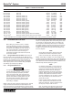
designated by the entry in the ordering code as shown
below:
MPP - XXX - XXX - XX - XX - XX - XX - XX - XXX - XX
Reservoir Option
2.2 MOUNTING INSTRUCTIONS
2.2.1 Reservoirs and tanks may be mounted to any
vertical surface. All units have 7/16 inch holes for attaching
bolts or screws. Cylindrical reservoirs have two holes, six
inches apart, drilled in the base bracket. All tanks have four
holes drilled in flanges according to the following rectangu-
lar dimensions:
9-7/8 wide by 7 inches high for T1 tanks
11-1/8 wide by 7 inches high for T2 tanks
16-3/8 wide by 7 inches high for T3 tanks
2.2.1.1 Make sure the mounting location allows clearance
for any accessories attached to the tank or reservoir. Oil
reservoirs and all tanks have a fill cup on the top. Make sure
there is enough room above the fill cup to permit personnel
to perform a filling operation without difficulty. Drill the re-
quired holes and attach the reservoir or tank to the vertical
surface. Securely tighten all attaching hardware. Make sure
that the reservoir or tank is level.
2.6 OIL TANK MAINTENANCE
(OPTIONS T1, T2 and T3) ....................................... 2-11
2.6.1 General ........................................................ 2-11
2.6.2 Oil Tank Maintenance .................................. 2-11
2.6.3 Disassembly of Oil Tanks ........................... 2-11
2.6.4 Assembly of Oil Tanks................................. 2-11
2.6.5 Oil Tank Parts List ....................................... 2-11
2.5 OIL RESERVOIR MAINTENANCE
(OPTIONS OP1 THROUGH OP4) ............................. 2-7
2.5.1 General .......................................................... 2-7
2.5.2 Oil Reservoir Maintenance ............................ 2-7
2.5.3 Disassembly of Oil Reservoir ....................... 2-7
2.5.4 Assembly of Oil Reservoir ............................. 2-7
2.5.5 Oil Reservoir Parts Lists ............................... 2-7
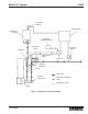
2.1.2 Tank Description. Tanks are rectangular
weldments used for holding oil. All tanks are equipped with
a sight glass to allow personnel to easily check the lubricant
level. A pad mounted to the tank base provides the neces-
sary tapped holes for either direct mounting of a manifold or
for installing hose or tubing to a remote-located manifold.
2.1.3 Reservoirs and Tanks Available. Table 2-1 lists the
tanks and reservoirs available for use. Listings in the option
column are used to identify the reservoir or tank selected
when a Modu-Flo system is ordered. The option used is
2.1.1 Reservoir Description. Reservoirs are cylindrical in
shape and are used for either grease or oil lubricants. If a
reservoir is to be used for grease it will be equipped with a
spring-loaded follower which will apply pressure on the
grease to force it into the pump. Reservoirs use cylinders
made of metal or plastic. If a metal cylinder is used, the
reservoir will be equipped with a level indicator to allow a
visual check of lubricant level. Plastic cylinders are clear,
allowing personnel to actually see the amount of lubricant
present. The base of all reservoirs has the necessary
tapped holes for either direct mounting of a manifold or for
installing hose or tubing to a remote-located manifold.