
User's Manual


Modu-Flo
®
System 42000
R
1.2 GENERAL SYSTEM OPERATION
1-2
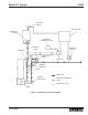
1.2.1 Figure 1-1 shows a functional schematic of a Modu-
Flo system.
1.2.1.1 The following steps outline the operating sequence
of a Modu-Flo system:
a. Lubricant stored in the reservoir or tank flows to the
manifold. The manifold may be mounted directly to the
reservoir or tank, or it may be mounted on a wall.
b. The manifold directs lubricant into the pump to fill the
pump chamber.
c. A controller energizes a solenoid valve to dispense and
the solenoid sends air or hydraulic fluid to the manifold.
Porting in the manifold directs the air or hydraulic fluid to
the pump, causing the pump to dispense lube to the
manifold outlet port.
d. When the controller releases the solenoid, air or
hydraulic fluid is redirected, causing the pump to retract.
On single-acting pneumatic pumps a spring pushes the
pump to the retracted position.
e. Lubricant from the reservoir flows through the manifold
and refills the empty chamber in the pump.
f. A pressure gauge, blowout disc, and high-pressure
switch are options which may be connected to the output
lube on the manifold. A signal from the pressure switch
can be used to actuate an alarm or warning light.
g. Low-level switch options are available for all tanks or
reservoirs. The switch provides an electrical signal
when lubricant level is low.