
User's Manual


Modu-Flo
®
System
6-4
42000
R
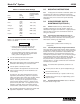
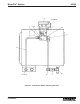
Table 6-4. High-Pressure Switch Parts List
Index
Number Part Number Description Quantity
521-001-220 HIGH-PRESSURE SWITCH ASSEMBLY (Option P1) --
1 542-210-120 SWITCH, Pressure 1
2 412-380-020 TEE, Male, 1/4 inch pipe 1
3 509-206-100 BLOWOUT ASSEMBLY, 1450 psi 1
4 -- . FITTING, Adapter 1
5 -- . DISC, Blowout 1
6 -- . NUT, Pressure relief 1
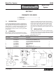
6.5 RESERVOIR BLOWOUT SWITCH
MAINTENANCE (OPTIONS P2 and P3)
6.5.1 General. Maintenance tips, disassembly, and
assembly instructions for reservoir blowout switches are
discussed in Paragraphs 6.5.2, and 6.5.3. A typical reservoir
with blowout switch is shown in Figure 6-3 and should be
referred to during the discussion.
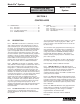
6.5.2 Reservoir Blowout Switch Maintenance Tips. No
maintenance is required on the blowout switch. If the switch
assembly is suspected to be defective, check all wiring to
the switch before removing any components.
WARNING
Disconnect and lock out all power from the
assembly before attempting disassembly.
Serious injury may result from electrical shock.
NOTE
Relieve system pressure before removing any
components.
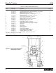
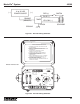
6.5.3 Assembly/Disassembly of Blowout Switch. Figure
6-3 shows a typical blowout switch mounted on a reservoir.
All components are connected by pipe threads and tubing
and are easily assembled or disassembled. The blowout
body (14) is connected to the IND port on the manifold. The
return elbow (15) is piped into the fill port of the reservoir.
Normally, the only components which may require removal
are the switch (5), indicator assembly (10), and blowout
disc. Access to these components is easily achieved after
removal of any connective tubing.
6.5.4 Reservoir Blowout Switch Parts Lists. Table 6-5
identifies the parts indexed on Figure 6-3.
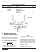
TANK OR
RESERVOIR
MANIFOLD
(REF)
LUBE OUTLET
EXISTING
LUBE
OUTLET
ELBOW
IND PORT
1
2
3
6
5
4
S.A.
Figure 6-2. High-Pressure
Switch (Rear View)
4-3/4”