
User's Manual


6-3
42000Modu-Flo
®
System
R
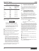
Table 6-3. Pressure Switch Settings
Maximum
Recommended
Disc Pressure Switch
Disc Rating Setting
Color psi (bar) psi (bar)
Yellow 1450 1160 (80)
(100)
Red 1750 1450 (100)
(121)
Orange 2050 1640 (113)
(141)
Aluminum 2350 1880 (130)
(162)
Blue 2950 2360 (163)
(203)
Purple 3250 2600 (179)
(224)
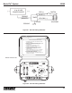
6.2.2.1 The adjustment procedure for the high-pressure
switch is as follows:
WARNING
• Disconnect and lock out all power from the
assembly before attempting disassembly.
Serious injury may result from electrical shock.
• To avoid possible system damage, change the
blowout disc to match the new pressure switch
setting. (Refer to Paragraph 6.2.1.)
a. Turn off electrical power to the lube system.
b. Connect control to pressure source.
c. With power disconnected, slide cover toward electrical
terminations while twisting it to overcome friction.
d. Connect power to terminals or leads.
e. Insert screwdriver into adjustment slot and turn clock-
wise to increase setting or counter-clockwise to de-
crease setting.
For setting on rise, apply desired pressure and turn
adjustment (clockwise facing cable end of pressure
switch) until switch clicks and/or tester confirms contact
transfer (Circuit across N.O. and COM. terminals
closes). For setting on fall, apply pressure equal to
normal system operating pressure. Reduce source
pressure to set point value. Turn adjustment counter-
clockwise until switch clicks and/or tester confirms
contact transfer (circuit across N.C. and COM. closes).
f. After completing adjustments, slide cover closed order
adjustment compartment. Recheck set point.
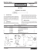
6.3 MOUNTING INSTRUCTIONS
6.3.1 All high-pressure switches and blowout options are
connected to the outlet of the manifold and mounted to
various locations on the reservoir or tank. Refer to assembly
Paragraphs 6.4.3, 6.5.3 and 6.6.3 for specific assembly
instructions.
6.4 HIGH-PRESSURE SWITCH
MAINTENANCE (OPTION P1)
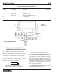
6.4.1 General. Maintenance tips, disassembly and
assembly procedures for the high-pressure switch are
discussed in Paragraphs 6.4.2 and 6.4.3. A typical pressure
switch is shown in Figure 6-2 and should be referred to
during the discussion.
6.4.2 High-Pressure Switch Maintenance Tips. No
maintenance is required on the high-pressure switch. If the
switch is suspected to be defective, check all wiring to the
switch before removing any components.
NOTE
Relieve system pressure before removing any
components.
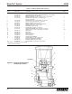
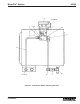
6.4.3 Assembly/Disassembly of High-Pressure Switch.
Figure 6-2 shows a typical high-pressure switch mounted to
a manifold. All components of the unit are connected by pipe
threads and are easily assembled or disassembled. The
blowout assembly (3) is connected to the IND port of the
manifold and the pressure switch (1) is connected by fittings
to the LUBE OUT port of the manifold. Normally, the only
components which may require removal or replacement are
the pressure switch (1) and the blowout disc (5). The
pressure switch (1) is easily screwed out after all electrical
connections are removed.
6.4.3.1 The blowout disc replacement procedure is as
follows:
a. Remove pressure relief nut (6) from adapter fitting (4).
b. Remove blowout disc (5).
c. Install new blowout disc (5) in pressure relief nut (6).
d. Install pressure relief nut (6) on adapter fitting (4) and
torque to 5 ft lbs.
6.4.4 Pressure Switch Parts Lists. Table 6-4 identifies
the parts indexed in Figure 6-2.