
User's Manual


42000Modu-Flo
®
System
R
OPERATION AND
SERVICE INSTRUCTIONS
Modu–Flo®
System
SECTION 1
INTRODUCTION
1.1 GENERAL................................................................... 1-1
1.1.1 Standard Components................................... 1-1
1.1.2 Modu-Flo Options ........................................... 1-1
1.2 GENERAL SYSTEM OPERATION .............................. 1-1
1.1 GENERAL
1.1.1 Standard Components. A wide choice of modular
components may be assembled to meet a given applica-
tion.
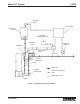
1.1.1.1 All Modu-Flo systems consist of the following
components:
a. A reservoir or tank for holding the lubricant. Reservoirs
are cylindrical units for grease or oil and are equipped
with a spring-loaded follower for grease applications.
Tanks are rectangular and are used for applications
using oil. Further information on reservoirs may be
found in Section 2.
b. A pump for dispensing a specific volume of lubricant.
Pumps may be pneumatically or hydraulically operated.
A selection of power ratios and displacement ranges
are available. Further information on pumps may be
found in Section 3.
c. A manifold attached to the base of the reservoir to
provide a mounting base for any pump. The manifold
has all the necessary porting to allow lubricant to flow
from the reservoir to the pump and from the pump to the
lubricant lines. Ports are also provided for pneumatic or
hydraulic inputs to operate the pump. Accessories such
as gauges and blowout assemblies are available and
may be connected to the manifold. If the pump is to be
located some distance from the reservoir, a wall-
mounted manifold is available. Further information on
manifolds is contained in Section 4.
1.1.2 Modu-Flo Options.
1.1.2.1 Options which are available for any system include
the following:
a. Low-level switches which mount to the reservoir or tank
and provide a low-level fault signal to a customer-
designated component. Level switch options are
described in Section 5.
b. High-pressure indicators which are installed into the
pump outlet circuit and provide an over-pressure signal
to external components. Pressure switch options are
discussed in Section 6.
c. A pneumatic solenoid valve which mounts directly to the
manifold. The solenoid valve is a three-way, normally-
closed type. Use of the solenoid allows the pump to be
cycled by various controller options. The solenoid is
equipped with a manual override button which may be
used to simplify system testing, line filling and line
bleeding.
d. Several types of controllers are used which can be
adapted to the system. Controller options are dis-
cussed in Section 8. Controllers available are as
follows:
(1) Timers which may be set to cycle the pump at given
intervals. Both AC and DC models are available.
(2) A TC-1000 timer can operate the lube system on
either a time or machine cycle basis. It is available
in 12 or 24 VDC or 115 or 230 VAC.
(3) A WMP Maxi-Monitor which provides a dispense
signal on either a time or machine cycle basis. The
WMP also monitors and displays the status of the
lube system it is controlling. The Maxi-Monitor is
available in either 115 or 230 VAC.
1-1