
User's Manual


6-1
42000Modu-Flo
®
System
R
OPERATION AND
SERVICE INSTRUCTIONS
Modu–Flo®
System
SECTION 6
HIGH-PRESSURE AND BLOWOUT SWITCHES
6.4.3 Assembly/Disassembly of High-Pressure
Switch ............................................................ 6-3
6.4.4 High-Pressure Switch Parts Lists ................ 6-3
6.5 RESERVOIR BLOWOUT SWITCH MAINTENANCE
(OPTIONS P2 and P3) .............................................. 6-4
6.5.1 General .......................................................... 6-4
6.5.2 Reservoir Blowout Switch
Maintenance Tips .......................................... 6-4
6.5.3 Assembly/Disassembly of Blowout Switch .. 6-4
6.5.4 Reservoir Blowout Switch Parts Lists........... 6-4
6.6 TANK BLOWOUT SWITCH MAINTENANCE
(OPTION P4) ............................................................. 6-6
6.6.1 General .......................................................... 6-6
6.6.2 Tank Blowout Switch Maintenance Tips ....... 6-6
6.6.3 Assembly/Disassembly of Blowout Switch .. 6-6
6.6.4 Tank Blowout Switch Parts List ..................... 6-6
6.1 DESCRIPTION .......................................................... 6-1
6.1.1 High-Pressure Switches ............................... 6-1
6.1.2 Blowout Switches .......................................... 6-1
6.1.3 Blowout Disc ................................................. 6-1
6.1.4 High-Pressure and Blowout Switch
Options .......................................................... 6-2
6.2 HIGH-PRESSURE SWITCH ADJUSTMENT............. 6-2
6.2.1 General .......................................................... 6-2
6.2.2 High-Pressure Switch Adjustment
Procedures .................................................... 6-2
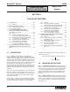
6.1 DESCRIPTION
6.1.1 High-Pressure Switches. High-pressure switches
may be plumbed into the lubricant output circuit to provide
an electrical signal when excessive pressure is being
approached. The pressure switch is factory set at 1150 psig
(79 bar) and is used with a standard blowout disc rated at
1450 psig (100 bar). When output pressure reaches 1150
psig (79 bar), contacts on the switch will actuate and provide
a warning signal to an external device. If the problem
causing the high pressure is not corrected, the pressure will
continue to rise. When pressure reaches 1450 psig
(100 bar) the blowout disc will rupture and relieve the
pressure. The setting of the pressure switch is adjustable.
Adjustment procedures are discussed in Paragraph 6.2.2.
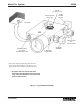
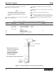
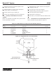
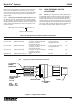
6.1.2 Blowout Switches. High-pressure blowout switch
assemblies may be plumbed into the lubricant circuit to
provide an electrical signal when the blowout disc has
ruptured. On these assemblies, a tubed blowout assembly
is used. The tubed blowout allows lubricant to flow from the
ruptured blowout disc, through tubing up to an indicator
assembly. The indicator assembly has a built-in check valve
which will allow the lubricant to reach a pressure sufficient
enough to extend a plunger. The extended plunger actuates
a switch which will allow a signal to be sent to an alarm or
other device. Lubricant from the indicator is directed through
tubing and is returned to the inlet port on the reservoir or
tank. The indicator will retain the plunger in the extended
position even if lubricant pressure is reduced. The plunger
must be manually depressed to release the switch and
return the indicator to its normal position.
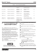
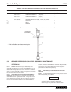
6.1.3 Blowout Disc. The standard blowout disc, rated at
1450 psig (100 bar), may be used on any unit. This assem-
bly does not provide any electrical signal when the blowout
pressure has been reached. The blowout disc will rupture at
the high pressure and the lubricant escaping from the
blown disc will provide a visual indication of failure. Discs
rated at higher pressures than 1450 psig (100 bar) are
available separately in kits of six. For identification pur-
poses, discs are color coded. Table 6-1 lists the discs
available and the kit number for each.
6.3 MOUNTING INSTRUCTIONS ................................... 6-3
6.4 HIGH-PRESSURE SWITCH MAINTENANCE
(OPTION P1) ............................................................. 6-3
6.4.1 General .......................................................... 6-3
6.4.2 High-Pressure Switch Maintenance Tips ..... 6-3
Table 6-1. Blowout Discs and Kits
Kit No.
Rating (contains
Disc Part No. Color psi (bar) 6 discs)
509-292-000 Yellow 1450 (100) 560-900-270
509-293-000 Red 1750 (121) 560-900-280
509-294-000 Orange 2050 (141) 560-900-290
509-295-000 Aluminum 2350 (162) 560-900-300
509-297-000 Blue 2950 (203) 560-900-320
509-298-000 Purple 3250 (224) 560-900-330