
User's Manual


Modu-Flo
®
System
5-6
42000
R
a. Disconnect and lock out all electrical power and air
supplies to the lube system.
b. Disconnect switch (1, Figure 5-3) from terminal box.
Remove switch (1) from bracket (2).
c. Remove retainer ring (3) and spring (5).
d. Remove three self-tapping screws (4) and bracket (2).
5.5.4 Assembly of Grease Reservoir Low-Level
Assembly.
5.5.4.1 The procedure for assembly of the grease reservoir
low-level assembly is as follows:
a. Attach bracket (2) to grease reservoir cover using three
self-tapping screws (4).
b. Place spring (5) over tip of level indicator.
c. Compress spring (5) and place retainer ring (3) be-
tween spring and tip of level indicator.
d. Attach switch (1) to bracket (2).
e. Wire switch (1) in accordance with local electrical codes.
Table 5-4. Grease Reservoir 15 Amp Low-Level Assembly Parts List
Item
Number Part Number Description Quantity
521-001-110 LOW-LEVEL SWITCH ASSEMBLY (Option L4) --
1 529-726-001 SWITCH 1
2 514-191-001 BRACKET 1
3 060251 RING, Retainer 1
4 415-210-010 SCREW, Self-tapping 3
5 542-939-000 SPRING 1
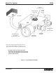
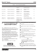
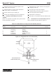
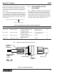
Figure 5-3. Grease Reservoir Low-Level Assembly
2
GREASE RESERVOIR
CABLE ASSEMBLY (REF)
GREASE RESERVOIR
CAP (REF)
3
1
5
4
5.5.5 Grease Reservoir Low-Level Assembly Parts List.
Table 5-4 identifies the parts indexed in Figure 5-3.