
User's Manual


5-5
42000Modu-Flo
®
System
R
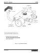
5.5 GREASE RESERVOIR LOW-LEVEL ASSEMBLY MAINTENANCE
(OPTION L4)
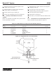
5.5.1 General. Maintenance tips, disassembly and
assembly procedures for low-level assembly option L4 are
discussed in Paragraphs 5.5.2, 5.5.3 and 5.5.4. A sectional
view of a typical assembly is shown in Figure 5-3 and should
be referred to during the discussion.
5.5.2 Grease Reservoir Low-Level Assembly Mainte-
nance Tips. No maintenance is required on the low-level
assemblies used on grease reservoirs. If the grease level
runs down and the assembly fails to perform as required,
the low level assembly may have to be disassembled to
replace a defective switch. Before attempting disassembly,
check all electrical connections to make sure they are secure
and check for any physical obstruction which might be
preventing the switch from operating.
5.5.3 Disassembly of Grease Reservoir Low-Level
Assembly.
5.5.3.1 The disassembly procedure for the grease reservoir
low-level assembly is as follows:
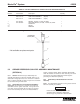
4
RESERVOIR
COVER (REF)
3
2
1
WARNING
Disconnect and lock out all power from the
assembly before attempting disassembly.
Serious injury may result from electrical shock.
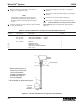
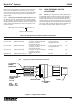
Table 5-3. Oil Tank and Reservoir 10-Watt Low-Level Assemblies Parts List
Item
Number Part Number Description Quantity
456-010-172 LOW-LEVEL ASSEMBLY (5 pint, 12 pint) --
456-010-173 LOW-LEVEL ASSEMBLY (20 pint) --
456-010-171 LOW-LEVEL ASSEMBLY (6 pint) --
1 541-603-001 SWITCH, 10 watts, 115 VAC, NC SPST 1
541-603-002 OPTIONAL SWITCH, 10 watts, 115 VAC, NO, SPST
2 COUPLING 1
3 NIPPLE 1
4 ADAPTER 1
Figure 5-2. Oil Tank and Reservoir 10-Watt Low-Level Assembly
*
*
*
* Not available as replacement parts.