
User's Manual


Modu-Flo
®
System
5-4
42000
R
5.4 OIL TANK RESERVOIR 10-WATT
LOW-LEVEL ASSEMBLY MAINTE-
NANCE (OPTIONS L5, L6 AND L7)
5.4.1 General. Maintenance tips, disassembly and
assembly procedures for low-level options L5, L6 and L7
are discussed in Paragraphs 5.4.2, 5.4.3 and 5.4.4. A
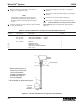
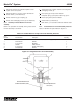
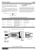
sectional view of a low-level assembly is shown in Figure 5-
2 and should be referred to during the discussion.
5.4.2 Oil Tank and Reservoir 10-Watt Low-Level
Assembly Maintenance Tips. No maintenance is required
on the 10-watt low-level assemblies used on oil tanks and
reservoirs. If the oil level runs down and the assembly fails
to perform as required the unit may have to be disas-
sembled to replace a defective switch. Before attempting
disassembly, check all electrical connections to make sure
they are secure and check for any physical obstructions
which might be preventing the float from operating.
5.4.3 Disassembly of Oil Tank and Reservoir 10-Watt
Low-Level Assemblies.
5.4.3.1 The disassembly procedure for oil tank and
reservoir 10-watt low-level assemblies is as follows:
WARNING
Disconnect and lock out all power from the
assembly before attempting disassembly.
Serious injury may result from electrical shock.
a. Turn off all electrical power and air supplies to the lube
system.
b. Disconnect the two 22 AWG wires from the terminal
box. Disconnect adapter (1, Figure 5-2) from the
conduit.
c. Remove the cover from the tank or reservoir (Refer to
Section 2.).
d. Unscrew nipple (2) from adapter (1). Be careful not to
twist the wires too much.
e. Unscrew nipple (2) from coupling (3).
f. Unscrew coupling (3) from switch (4).
g. Unscrew adapter (1) from the reservoir cover.
5.4.4 Assembly of Oil Tank and Reservoir 10-Watt Low-
Level Assemblies.
5.4.4.1 The assembly procedure is as follows:
NOTE
The procedure listed below is based on
installing a new assembly in a tank or reservoir.
If your assembly was removed for repairs,
steps
a and b do not apply.
a. Remove the cover from the reservoir (Refer to Section
2.).
b. Remove the 1/4 inch pipe plug from the cover. Screw
adapter (1, Figure 5-2) in and tighten it securely.
c. Guide the two 22 AWG wires from switch (4) through
coupling (3). Screw coupling (3) onto switch (4) and
tighten securely.
d. Guide two 22 AWG wires through nipple (2). Screw
nipple into coupling (3).
e. Guide the two 22 AWG wires through adapter (1). Screw
nipple into adapter (1). Be careful not to twist the wires
too much. Tighten the connection.
f. Connect switch (4) in accordance with local electrical
codes.
5.4.5 Oil Tank and Reservoir 10-Watt Low-Level
Assemblies Parts List. Table 5-3 identifies the parts
indexed in Figure 5-2.