
User's Manual


5-3
42000Modu-Flo
®
System
R
c. Screw low-level lower assembly (4) into low-level
adapter (3) and tighten securely.
e. Screw switch adapter (2) into switch (1) and tighten
securely.
f. Screw union nut (5) onto switch adapter (2) and tighten
securely.
g. Install cover on reservoir (Refer to Section 2.).
h. Wire switch in accordance with local electrical codes.
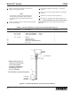
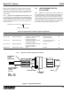
5.3.5 Oil Tank and Reservoir 15 Amp Low-Level Assem-
blies Parts List. Table 5-2 identifies the parts indexed in
Figure 5-1.
NOTE
If float portion of low-level lower assembly was
removed during disassembly, apply Locktite to
the attaching bolt and securely attach the float to
the arm.
d. Insert the actuating rod, part of low-level lower assembly
(4), into this assembly.
Table 5-2. Oil Tank and Reservoir 15 Amp Low-Level Assemblies Parts List
Item
Number Part Number Description Quantity
521-001-030 LOW-LEVEL ASSEMBLY (5 pint, 12 pint) --
521-001-040 LOW-LEVEL ASSEMBLY (20 pint) --
521-001-050 LOW-LEVEL ASSEMBLY (6 pint) --
1 514-116-001+ SWITCH 1
2 ADAPTER, Switch 1
3 ADAPTER, Low-level 1
4 LOW-LEVEL LOWER ASSEMBLY 1
5 NUT, Union 1
*
*
*
*
2
3
5
1
COVER (REF)
4
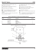
LOCKTITE
USED AT
ASSEMBLY
+ When replacing item (1)
switch only, remove lock
nut from new switch
plunger housing before
assembling switch to
item (2) adapater.
Figure 5-1. Oil Tank and Reservoir 15 Amp Low-Level Assembly
* Not available as replacement parts.