
User's Manual


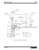


Modu-Flo
®
System 42000
R
ii
LIST OF TABLES
Number Title Page
2-1. Reservoirs and Tanks......................................... 2-2
2-2. Grease Reservoir Parts List ............................... 2-4
2-3. Oil Reservoir Parts Lists ..................................... 2-8
2-4. Oil Tank Parts List ............................................. 2-12
3-1. Pumps................................................................. 3-2
3-2. Pneumatic Pump Parts List ................................ 3-5
3-3. Hydraulic Pump Options H1 and H3
Parts List ........................................................... 3-10
3-4 Hydraulic Pump Option H2 Parts List ............... 3-14
4-1. Operating Ports on Modu-Flo Manifolds ............. 4-2
4-2. Manifolds and Manifold Accessories.................. 4-2
5-1. Low-Level Switch Assemblies ........................... 5-2
5-2. Oil Tank and Reservoir 15 Amp Low-Level
Assemblies Parts List ........................................ 5-3
Number Title Page
5-3. Oil Tank and Reservoir 10-Watt Low-Level
Assemblies Parts List ........................................ 5-5
5-4. Grease Reservoir Low-Level Assembly
Parts List ............................................................. 5-6
6-1. Blowout Discs and Kits....................................... 6-1
6-2. High-Pressure and Blowout Switch
Assemblies ......................................................... 6-2
6-3. Pressure Switch Settings ................................... 6-3
6-4. High-Pressure Switch Parts List ........................ 6-4
6-5. Reservoir Blowout Switch Parts List .................. 6-5
6-6. Tank Blowout Switch Parts List........................... 6-6
7-1. Pneumatic Solenoid Parts List ........................... 7-1
10-1. Modu-Flo Troubleshooting ............................... 10-1