
User's Manual


42000Modu-Flo
®
System
R
OPERATION AND
SERVICE INSTRUCTIONS
Modu–Flo®
System
4-1
SECTION 4
MANIFOLDS
4.1 DESCRIPTION ........................................................... 4-1
4.1.1 General ........................................................... 4-1
4.2 PREPARATION FOR USE .......................................... 4-1
4.2.1 Mounting ......................................................... 4-1
4.2.2 Connection to Other Components ................. 4-1
4.3 MAINTENANCE .......................................................... 4-1
4.1 DESCRIPTION
4.1.1 General. Two modular-design manifolds are
available. Either manifold is designed to have any of the
pneumatic or hydraulic pumps mount directly to it. The
pump-to-reservoir manifold attaches directly to the base of
the lubricant reservoir or tank. The pump-to-wall manifold is
used to mount the lubricant pump in a remote location,
separate from the lubricant reservoir or tank.
4.1.1.1 The manifolds contain the pneumatic (or hydraulic)
porting and lubricant lines necessary to operate the pump
and to direct the lubricant flow. A shutoff is built into the
manifold to prevent lubricant from leaking from the reservoir
or tank when the pump is removed.
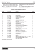
4.1.1.2 Table 4-1 lists the operating ports used on the
manifolds. Each port is identified by stamped lettering.
Table 4-2 lists the part numbers of the manifolds accesso-
ries. Manifolds and accessories can be ordered separately
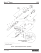
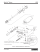
or as a combination package. Figure 4-1 shows a typical
manifold with various accessories connected to the lube
ports.
4.2 PREPARATION FOR USE
4.2.1 Mounting. Pump-to-reservoir manifolds mount
directly to the base of the reservoir or tank with two 3/8-16
socket-head screws. Pump-to-wall manifolds require that
the surface that the manifold will be attached to has two 3/8-
16 tapped holes 2-1/4 inches apart. The manifold must be
mounted so that when the pump is mounted the enclosure
screw on the pump will be on top. This will ensure proper
bleeding and priming of the system.
4.2.2 Connection to Other Components. Four 1/4-20
tapped holes are provided on the manifold for pump
attachment. The holes are laid out in a way that prevents the
pump from being mounted incorrectly. The operating ports,
listed in Table 4-1, must be connected by hose or tubing to
their appropriate locations.
4.3 MAINTENANCE
4.3.1 There is little maintenance required on the mani-
fold assemblies. All fittings and accessories used on the
unit should be tightened to avoid leakage. If any accessory
shows evidence of failure it may be removed by simply
unscrewing it from the manifold. Refer to disassembly
procedures in Section 2 for draining techniques. The pump
does not need to be removed from the manifold but it may
be desired if space is limited.
NOTE
Ensure all lubricant is drained from reservoir
before removing manifold.