
User's Manual


Modu-Flo
®
System 42000
R
3-10
f. Install jam nut (19) and two new gaskets (18), one on
each side of jam nut, on adjustment screw (10). Butt
adjustment screw cap (20) against jam nut (19) and
turn adjustment screw (10) until the length it extends
beyond the jam nut is the same as the length recorded
during disassembly.
g. Install adjustment screw cap (20) on adjustment screw
(10).
h. Install new o-ring (23) on check seat (22) and install
seat assembly into pump body.
i. Install steel ball (24) and check valve spring (13) into
body (7). Place new gasket (12) on enclosure screw
(11). Screw enclosure screw into body (7) and tighten
securely.
j. Install three new o-rings (15) and one o-ring (16) into
body (7). Securely attach pump assembly to manifold
with four socket-head screws (8).
3.4.4.2 When the assembly steps listed above have been
completed, adjust the pump output as described in Para-
graph 3.2.2.
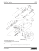
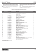
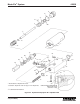
3.4.5 Hydraulic Pump Options H1 and H3 Parts List.
Table 3-3 identifies the parts indexed in Figure 3-3.
Table 3-3. Hydraulic Pump Options H1 and H3 Parts List
Item
Number Part Number Description Quantity
521-000-011 PUMP ASSEMBLY, HLJ-5 (Option H1) --
521-005-900 PUMP ASSEMBLY, HLJ-5X (Option H3) --
1 PISTON, Lube (HLJ-5) 1
2 521-000-190 PISTON, Hydraulic (HLJ-5) 1
3 411-101-630+ PIN, Groove, part of kit 560-001-051 (HLJ-5) 1
4 422-021-110+ O-RING, Part of kit 560-001-051 (HLJ-5) 1
5 422-011-160+ O-RING, Part of kit 560-001-051 (HLJ-5) 1
422-021-160+ O-RING, Part of kit 560-001-940 (HLJ-5X) 1
6 521-000-180 CAP, Cylinder 1
7 BODY, Pump, HLJ-5 1
8 419-130-070 SCREW, Socket-head, 1/4-20 x 1-1/4 inch, part of repair kit 560-001-051 4
9 422-011-140+ O-RING, Part of kit 560-001-051 (HLJ-5) 1
422-021-140+ O-RING, Part of kit 560-001-940 (HLJ-5X) 1
10 521-003-000 SCREW, Adjustment 1
11 521-008-460 SCREW, Enclosure 1
12 500-132-000+ GASKET, Part of kits 560-001-051 and 560-001-940 1
13 511-893-000+ SPRING, Check valve, part of kits 560-001-051 and 560-001-940 1
14 401-030-030+ BALL, Steel, 3/16 inch, part of kits 560-001-051 and 560-001-940 1
15 423-700-113+ O-RING, Part of kits 560-001-051 and 560-001-940 3
16 423-700-114+ O-RING, Part of kits 560-001-051 and 560-001-940 1
17 521-003-030 BODY, Adjustment screw (HLJ-5) 1
521-005-710 BODY, Adjustment screw (HLJ-5X) 1
18 439-040-050+ GASKET, Stat-O-Seal, part of kit 560-001-051 (HLJ-5) 2
439-050-050+ GASKET, Stat-O-Seal, part of kit 560-001-940 (HLJ-5X) 2
19 410-702-028 NUT, Jam, Part of Kit 560-001-051 1
20 521-002-970 CAP, Adjustment screw (HLJ-5) 1
521-010-360 CAP, Adjustment screw (HLJ-5X) 1
21 527-000-790+ O-RING, Part of kit 560-001-051 (HLJ-5) 1
22 521-008-450+ SEAT, Check valve, part of kits 560-001-051 and 560-001-940 1
23 422-010-080+ O-RING, Part of kits 560-001-051 and 560-001-940 1
25 423-700-057+ RING, Backup, part of kit 560-001-940 (HLJ-5X) 2
26 423-700-060+ O-RING, Part of kit 560-001-940 (HLJ-5X) 1
27 PISTON (HLJ-5X) 1
28 423-700-058+ RING, Backup, part of kit 560-001-940 (HLJ-5X) 2
29 423-700-059+ O-RING, Part of kit 560-001-940 (HLJ-5X) 1
30 521-000-050 SCREW, Enclosure 1
31 401-010-010 BALL, Steel 1/8” Dia., Part of Kit 560-001-051 1
32 417-450-020 SCREW, Set 10-32”x1/4” 1
-- 560-001-051 REPAIR KIT (consists of Items 3, 4, 5, 8, 9, 12 thru 16, 18, and 21 thru 23) 1
-- 560-001-940 REPAIR KIT (consists of Items 5, 9, 12 thru 16, 18, 22 thru 26, 28 1
and 29)
-- 521-001-391 PUMP ADJ. ASSEMBLY (consists of Items 10 & 17 thru 20) (HLJ-5) 1
* Not Available as Replacement Parts.
+ Included in Repair Kit.
*
*
*