
User's Manual


42000Modu-Flo
®
System
R
3-9
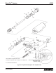
3.4 HYDRAULIC PUMP MAINTENANCE
(OPTIONS H1 and H3)
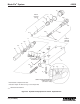
3.4.1 General. Maintenance tips, disassembly and
assembly procedures for Options H1 and H3 hydraulic pump
are discussed in Paragraphs 3.4.2 through 3.4.4. An
exploded view of the pump is shown in Figure 3-3 and
should be referred to during the discussion.
3.4.2 Hydraulic Pump Options H1 and H3 Maintenance
Tips.
3.4.2.1 The only maintenance required on the hydraulic
pump Options H1 and H3 is to check for the following:
a. Check four socket-head screws (8, Figure 3-3) to make
sure they are tight. Loose screws could allow hydraulic
fluid and/or lubricant to leak between the pump and the
manifold. This condition could result in erratic pump
output.
b. Check for leakage past gasket (12). Replace gasket if
required.
c. Check jam nut (19) to make sure that it is tight against
adjustment screw body (17). If the jam nut is loose, the
adjustment screw (10) could rotate and cause the pump
output to change. This condition could also result in
lubricant leakage or in air being sucked into the lubri-
cant.
3.4.2.2 If internal components of the pump are defective it
will usually result in erratic pump operation or output. Section
10 of this manual lists causes and solutions for problems
which could occur in the Modu-Flo system. Before disas-
sembling any pump, refer to Section 10. The problem may
be caused by other conditions which can be checked first
before disassembling the pump.
3.4.3 Disassembly of Hydraulic Pump Options H1 and
H3. The procedure below describes complete disassembly
of a pump. However, you only need to disassemble to your
specific area of concern.
(2) Remove jam nut (19) and two gaskets (18). Discard
gaskets (18).
(3) Remove adjustment screw (10) by screwing it
towards the hex portion of the adjustment screw
body (17) until it is free.
d. Remove cylinder cap (6) from body (7). Remove and
discard o-ring (5).
e. Removal of the piston and its associated components is
different for each option. Perform the appropriate
following steps:
(1) For Option H1, use a wood dowel or a soft rod to
push hydraulic piston (2) and lube piston (1) from
pump body (7). Remove and discard o-rings (4) and
(21). Inspect piston (2) and pump body (7) inner
diameter for scoring or wear marks. If damage is
present the pump assembly cannot be serviced and
should be replaced.
(2) For Option H3, use a wood dowel or a soft rod to
push the piston (27) from the pump body (7).
Remove and discard o-rings (26 and 29) and
backup rings (25 and 28). Inspect piston (27) and
pump body (7) inner diameter for scoring or wear
marks. If damage is present, the pump assembly
cannot be serviced and should be replaced.
f. For the H1 option only, separate hydraulic piston (2) and
lube piston (1) by removing groove pin (3).
3.4.4 Assembly of Hydraulic Pump Options H1 and H3.
NOTE
Use new o-rings and gaskets when assembling
pump. Lubricate all o-rings and sliding parts
with the lubricant which is used in the system.
3.4.4.1 Assemble the hydraulic pump Options H1 and H3
according to the following procedure:
a. For the H1 option only, insert lube piston (1) into hydrau-
lic piston (2). Install groove pin (3) to secure the assem-
bly.
b. Assembly of the piston and its associated components
is different for each option. Perform the appropriate
following steps:
(1) For Option H1, install new o-ring (4) on hydraulic
piston (2). Install new o-ring (21) on lube piston (1).
Insert pistons into body (7).
(2) For Option H3, install new o-ring (26) and backup
rings (25) on cylinder cap end of piston (27). Install
new o-ring (29) and backup rings (28) on the other
end of the piston (27).
c. Install new o-ring (5) on cylinder cap (6). Screw cylinder
cap (6) into body (7) and securely tighten it.
d. Insert smaller end of adjustment screw (10) into
adjustment screw body (17). Rotate adjustment screw
(10) until smaller end is protruding from hex portion of
adjustment screw body (17).
e. Install new o-ring (9) on adjustment screw body (17) and
install adjustment screw body in body (7). Tighten
securely.
3.4.3.1 The disassembly procedure for the hydraulic pump
Options H1 and H3 is as follows:
a. Separate pump from manifold by removing four socket-
head screws (8). Remove and discard three o-rings (15)
and one o-ring (16).
b. Remove enclosure screw (11). Remove and discard
gasket (12), check valve spring (13), steel ball (24),
check seat (22), and o-ring (23).
c. Remove adjustment screw body (17) and o-ring (9) from
body (7). Discard o-ring (9). Removal of adjustment
screw (10) from adjustment screw body (17) will change
output setting when pump is reassembled. If adjust-
ment screw (10) requires removal, perform the follow-
ing:
(1) Remove adjustment screw cap (20) from adjust-
ment screw (10). Butt the adjustment screw cap
(20) against jam nut (19) and use the stamped
numbers on the cap to measure how far the
adjustment screw (10) extends from the jam nut.
Record this dimension.