
User's Manual


Modu-Flo
®
System 42000
R
3-4
e. Insert wooden dowel or soft rod into pump body (10) and
push lube piston (5) until cylinder cap (3) is out of air
cylinder (7). Remove and discard o-ring (2) from cylinder
cap (3).
f. Continue to push lube piston (5) through pump body
(10) until air piston (1) is exposed and can be removed
from air cylinder (7). Remove air piston (1), lube piston
(5), and piston-return spring (24) from air cylinder (7).
g. Remove retainer ring (25) and spring retainer (26) from
air piston (1).
h. Remove retainer ring (27) to separate lube piston (5)
from air piston (1). Remove and discard o-rings (6 and
28).
3.3.4 Assembly of Pneumatic Pump.
3.3.4.1 Assemble the pneumatic pump according to the
following procedure:
NOTE
Use new o-rings, gaskets and return spring
when assembling pump. Lubricate all o-rings
and sliding parts with the lubricant which is
used in the system.
a. Install new o-ring (6) on lube piston (5).
b. Install new o-ring (28) on air piston (1). Install lube
piston (5) into air piston (1) and secure with retainer ring
(27).
c. Install spring retainer (26) in air piston (1) and secure
with retainer ring (25).
d. Install piston-return spring (24) in air cylinder (7). Push
air piston (1) through air cylinder (7) and into pump body
(10).
e. Install new o-ring (2) on cylinder cap (3) and secure in
air cylinder (7) with retainer ring (4).
f. Insert smaller end of adjustment screw (13) into
adjustment screw body (19). Rotate adjustment screw
(13) until smaller end is protruding from hex portion of
adjustment screw body (19).
g. Install new o-ring (12) on adjustment screw body (19)
and install adjustment screw body in pump body (10).
Tighten securely.
h. Install jam nut (21) and two new gaskets (20), one on
each side of jam nut, on adjustment screw (13). Butt
adjustment screw cap (22) against jam nut (21) and turn
adjustment screw (13) until the length it extends beyond
the jam nut is the same as the length recorded during
disassembly.
i. Install adjustment screw cap (22) on adjustment screw
(13).
j. Install new o-ring (30) on check seat (29) and install
seat into pump body.
k Install steel ball (32) and check valve spring (16) into
pump body (10). Place new gasket (15) on enclosure
screw (14). Install enclosure screw (14) into pump body
(10) and tighten securely.
l Install three new o-rings (9) and one new o-ring (18) into
pump body (10). Securely attach to manifold with four
socket-head screws (11).
3.3.4.2 When the assembly steps listed above have been
completed, adjust the pump output as described in Para-
graph 3.2.2.
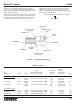
3.3.5 Pneumatic Pump Parts List. Table 3-2 identifies
the parts indexed in Figure 3-2.