
User's Manual


42000Modu-Flo
®
System
R
3-3
3.2 PREPARATION FOR USE
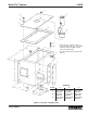
3.2.1 Mounting. Any pump mounts directly to any manifold
with four socket-head capscrews. Care must be taken to
ensure that the outlet of the manifold is lined up with the inlet
on the pump. The face of the pump which mates with the
manifold has several o-rings. When the pump is being
installed, care must be taken to ensure these o-rings are not
moved out of position. The o-rings provide a seal for the
movement of air and lubricant between the manifold and
pump. If an o-ring is missing, air or lubricant may leak. After
being secured to the manifold, no further connections can be
made to the pump.
3.2.2 Output Adjustment. Adjustment of the pump output
may be made with the pump removed from or still attached
to the manifold.
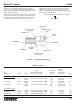
3.2.2.1 The procedure for output adjustment is listed below.
The items referenced are found in Figure 3-2. The adjust-
ment procedure is the same for both pneumatic and hydrau-
lic pumps.
a. Remove adjustment cap (22) from adjustment screw
(13), holding jam nut (21) if necessary.
b. Butt adjustment cap (22) against jam nut (21) and use
the stamped numbers on the cap to determine how
much adjustment is needed.
c. Loosen jam nut (21) and use a flat screwdriver to turn
adjustment screw (13). Turn adjustment screw in for
less output, turn out for more output.
d. Tighten jam nut (21) and install adjustment cap (22)
over the adjustment screw (13).
3.2.2.2 When adjusting pump output, one complete turn of
the adjusting screw will change the output by the following
amounts:
a. 0.0018 cubic inch for pump options A1 and A2.
b. 0.006 cubic inch for pump options A3 and A4.
c. 0.009 cubic inch for pump options A5 and A6.
d. 0.0018 cubic inch for pump option H1.
e. 0.006 cubic inch for pump option H2 and H3.
3.3 PNEUMATIC PUMP MAINTENANCE
(OPTIONS A1 THROUGH A6)
3.3.1 General. Maintenance tips, disassembly and
assembly procedures for pneumatic pumps are discussed
in Paragraphs 3.3.2 through 3.3.4. An exploded view of a
typical pneumatic pump is shown in Figure 3-2 and should
be referred to during the discussion.
3.3.2 Pneumatic Pump Maintenance Tips.
3.3.2.1 The only maintenance required on the pneumatic
pump is to check for the following:
a. Check four socket-head screws (11, Figure 3-2) to make
sure they are tight. Loose screws could allow air and/or
lubricant to leak between the pump and the manifold.
This condition could result in erratic pump output.
b. Check jam nut (21) to make sure it is tight against
adjustment screw body (19). If the jam nut is loose, the
adjustment screw (13) could rotate and cause the pump
output to change. This condition could also result in
lubricant leakage or in air being sucked into the lubri-
cant.
3.3.2.2 If internal components of the pump are defective it
will usually result in erratic pump operation or output. Section
9 of this manual lists causes and solutions for problems
which could occur in the Modu-Flo system. Before disas-
sembling any pump, refer to Section 10. The problem may
be caused by other conditions which can be checked first
before disassembling the pump.
3.3.3 Disassembly of Pneumatic Pump. The procedure
below describes complete disassembly of a pump. How-
ever, you only need to disassemble to your specific area of
concern.
3.3.3.1 The disassembly procedure for the pneumatic
pump is as follows:
NOTE
Figure 3-2 shows air cylinder (7) separated from
pump body (10). To achieve disassembly to this
level requires special tools to remove air cylin-
der retainer (23). Normally, this level of disas-
sembly is only performed at the factory. If scoring
or wear marks are evident on the inner diameter
of air cylinder (7) or pump body (10), the pump
assembly cannot be serviced and should be
replaced.
a. Separate pump from manifold by removing four socket-
head screws (11, Figure 3-2). Remove and discard three
o-rings (9) and one o-ring (18).
b. Remove enclosure screw (14). Remove and discard
gasket (15). Remove check valve spring (16), ball (32),
and check seat (29). Remove and discard o-ring (30)
from seat (29).
c. Remove adjustment screw body (19) and o-ring (12)
from pump body (10). Discard o-ring (12). Removal of
adjustment screw (13) from adjustment screw body (19)
will change output setting when pump is reassembled.
If adjustment screw (13) requires removal, perform the
following:
(1) Remove adjustment screw cap (22) from adjust-
ment screw (13). Butt the adjustment screw cap
(22) against jam nut (21) and use the stamped
numbers on the cap to measure how far the
adjustment screw (13) extends from the jam nut.
Record this dimension.
(2) Remove jam nut (21) and two gaskets (20). Discard
gaskets.
(3) Remove adjustment screw (13) by screwing it
towards the hex portion of the adjustment screw
body (19) until it is free.
d. Remove retainer ring (4).