
User's Manual
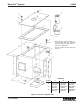


Modu-Flo
®
System 42000
R
3-2
3.1.1.4 In pneumatically-operated systems, pressure
surges often occur when the solenoid is energized. These
surges can be minimized by installing air flow devices in the
solenoid pneumatic lines.
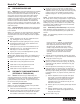
3.1.1.5 Table 3-1 lists the available pumps along with other
data. Note that the part number on the pneumatic pump is
the same for two different pump models. This is because
any pneumatic pump may be used as either single- or
double-acting. Listings in the option column are used to
identify the pump selected when a Modu-Flo system is
ordered. The option used is designated by the entry in the
ordering code as shown below:
MPP - XXX - XXX - XX - XX - XX - XX - XX - XXX - XX
Pump Option
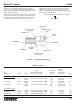
Figure 3-1. Typical Pump Operation
Table 3-1. Pumps
Input
Volume
Output Maximum Per Full
Part Displacement Range Strokes/ Stroke/Cycle
Number Model Action cu in (cm
3
) per stroke Minute cu.in. (cm
3
) Option
A. Pneumatic Pumps
521-000-001 AL-5 Single 0.010 to 0.030 (0.164 to 0.492) 65 1.06 (17.4) A1
Double 100 2.09 (34.3)
521-000-021 AL-25 Single 0.030 to 0.120 (0.492 to 1.966) 25 4.20 (68.8) A3
Double 100 8.28 (135.7)
521-000-041 AL-50 Single 0.060 to 0.240 (0.983 to 3.933) 20 8.40 (137.6) A5
Double 60 16.56 (271.4)
B. Hydraulic Pumps
521-000-011 HLJ-5 Double 0.010 to 0.030 (0.164 to 0.492) 100 0.35 (5.7) H1
521-000-031 HLJ-25 Double 0.030 to 0.120 (0.492 to 1.966) 50 1.38 (22.6) H2
521-005-900 HLJ-5X Double 0.030 to 0.092 (0.492 to 1.51) 100 1.28 (21.0) H3
LUBE INLET
PORT
LUBE OUTLET
PORT
SINGLE ACTING
(S.A.) PORT
CHAMBER (A)
AIR PISTON
RETURN
SPRING
DOUBLE ACTING
(D.A.) PORT
LUBE PISTON
CHAMBER (B)
CHECK
VALVE
CHAMBER (C)