
User's Manual
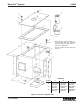


42000Modu-Flo
®
System
R
OPERATION AND
SERVICE INSTRUCTIONS
Modu–Flo®
System
3-1
SECTION 3
PUMPS
3.1 DESCRIPTION .......................................................... 3-1
3.1.1 General .......................................................... 3-1
3.2 PREPARATION FOR USE ......................................... 3-3
3.2.1 Mounting ........................................................ 3-3
3.2.2 Output Adjustment ......................................... 3-3
3.3 PNEUMATIC PUMP MAINTENANCE
(OPTIONS A1 THROUGH A6) ................................... 3-3
3.3.1 General .......................................................... 3-3
3.3.2 Pneumatic Pump Maintenance Tips ............ 3-3
3.3.3 Disassembly of Pneumatic Pump ................ 3-3
3.3.4 Assembly of Pneumatic Pump ..................... 3-4
3.3.5 Pneumatic Pump Parts List .......................... 3-4
3.4 HYDRAULIC PUMP MAINTENANCE
(OPTIONS H1 and H3).............................................. 3-9
3.4.1 General .......................................................... 3-9
3.4.2 Hydraulic Pump Options H1 and H3
Maintenance Tips .......................................... 3-9
3.4.3 Disassembly of Hydraulic Pump
Options H1 and H3 ....................................... 3-9
3.4.4 Assembly of Hydraulic Pump Options H1
and H3 ........................................................... 3-9
3.4.5 Hydraulic Pump Options H1 and H3
Parts List ..................................................... 3-10
3.5 HYDRAULIC PUMP MAINTENANCE
(OPTION H2) ........................................................... 3-13
3.5.1 General ........................................................ 3-13
3.5.2 Hydraulic Pump Option H2
Maintenance Tips ........................................ 3-13
3.5.3 Disassembly of Hydraulic Pump
Option H2 .................................................... 3-13
3.5.4 Assembly of Hydraulic Pump Option H2 .... 3-13
3.5.5 Hydraulic Pump Option H2 Parts List ......... 3-14
3.1 DESCRIPTION
3.1.1 General. There are six models available for use.
Three models are pneumatically operated and three are
hydraulically operated. The pneumatic models may be
single or double acting. An internal spring will return the
piston to the reload position in single-acting pumps. All
hydraulic models are double-acting.
3.1.1.1 All models are designed to mount directly to either
the pump-to-reservoir manifold or the pump-to-wall mani-
fold. When the pump is properly mounted on a manifold, the
manifold will have all the porting for air and lubricant
connections to and from the pump.
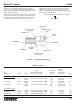
3.1.1.2 Operating sequences for single-acting and double-
acting pumps are listed below. Figure 3-1 shows a sec-
tional view of a typical pump and will help in understanding
pump operation.
a. With single-acting models, air under pressure is
supplied through the inlet port (SA) to chamber (C). This
moves the air and lube pistons to the right. This closes
the lube inlet port and forces the lubricant already in
chamber (B) past the check valve and into the system.
Air in chamber (A) must vent out port (DA). A plastic pipe
plug with a vent hole is installed in port (DA). After a
preset time interval the solenoid valve shuts off the air
supply and vents chamber (C) through port (SA). The
spring returns the air and lube pistons, opening
chamber (B) to the lube reservoir.This completes a
single pump cycle and chamber (B) is primed, ready for
the next cycle.
b. The double-acting models have an additional air or
hydraulic supply line connected to port (DA). When the
pistons have been moved to the right, air or hydraulic
supply to port (SA) is shut off and vented. Then, air or
hydraulic fluid under pressure is supplied to port (DA),
which returns the pistons to their original position. This
more powerful return action allows an increased cycle
rate of the pump.
3.1.1.3 All pneumatic pumps have a lube-to-air pressure
ratio of 30:1. The pumps operate on input pressure ranging
from 40 to 150 psi (3 to 10 bar). The HLJ-5M and HLJ-25M
hydraulic pumps have a lube-to-hydraulic ratio of 5.5:1. The
HLJ-5X has a lube-to-hydraulic ratio of 2.2:1. The hydraulic
pumps operate on input pressures ranging from 200 to
2000 psi (14 to 138 bar). It should be noted that lower input
pressures may prevent the pumps from building sufficient
pressure to crack a rupture disc or activate a high-pressure
device. In pneumatic systems, with an inlet air pressure of
40 psi (3 bar), only 1200 psi (83 bar) could be developed. In
hydraulic systems, with 200 psi (14 bar) only 1100 psi
(76 bar) could be developed. Neither of these pressures
would be high enough to crack a 1450 psi disc. The system
could be blocked and not functioning without giving any
indication to plant personnel. The supply pressure, either
penumatic or hydraulic, should be adjusted high enough to
ensure that a blocked line will cause sufficient pressure to
be developed.