
User's Manual


42000Modu-Flo
®
System
R
2-11
2.6 OIL TANK MAINTENANCE
(OPTIONS T1, T2 and T3)
2.6.1 General. Maintenance tips, disassembly and as-
sembly procedures for oil tanks are discussed in Para-
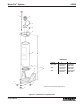
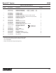
graphs 2.6.2, 2.6.3 and 2.6.4. An exploded view of a typical oil
tank is shown in Figure 2-3 and should be referred to during
the discussion.
2.6.2 Oil Tank Maintenance.
2.6.2.1 Maintenance on the oil tanks consists of the follow-
ing:
a. Visually check for oil leakage between the tank (9, Figure
2-3), the pump mounting pad (12) and the level sight
glass (11). Leakage in either of these areas indicates
the components are loose or that gasket (10) or o-ring
(13) is defective. The cover (1) will need to be removed
to either tighten the components or replace defective
seals.
b. Visually check fill screen (4) to make sure it is not
clogged. If necessary, remove the screen for cleaning.
c. Check that the tank is securely fastened to the wall or
supporting structures. Securely tighten any loose
attaching hardware.
WARNING
Disconnect and lock out power before opening
electrical enclosures or conduit connections.
Serious injury may result from electrical shock.
2.6.3 Disassembly of Oil Tanks. Figure 2-3 shows a
typical oil tank but does not include other Modu-Flo compo-
nents which may be mounted to the tank. These compo-
nents include the manifold, pump, level switches and blow-
out switches. Disassembly of tank may require that some of
these components be removed. The manifold and pump do
not normally require removal, but may be removed if desired.
The level and blowout switches may or may not require
removal, depending on the level of disassembly required.
The electrical connections to the switches should be discon-
nected in order to remove various parts without restriction of
movement by the electrical cord. The removal of these com-
ponents is explained in other sections of the manual. Refer
to the table of contents to find where these components are
discussed.
2.6.3.1 The disassembly procedure may be performed with
the tank mounted to the mounting surface. However, some
mounting locations may be too restrictive to provide access
to all components. If your particular installation requires
dismounting of the tank, make sure the tank is drained of
lubricant before removing the attaching hardware. This will
reduce the weight of the tank and reduce the chance of spill-
age. The disassembly procedure is as follows:
a. Remove pipe plug (3, Figure 2-3) from base of tank
weldment (9) and allow oil to drain into bucket or similar
container. Properly dispose of emptied oil.
b. Remove self-threading screws (2) attaching cover (1) to
tank weldment (9) and remove cover and cover gasket
(6).
c. Remove fill screen (4) from fill cup (5) and clean screen.
d. Remove two screws (7) and aluminum gaskets (8) to
release pump mounting pad (12) from tank weldment
(9). Remove and discard o-ring (13) from pump mount-
ing pad (12).
2.6.4.2 When the assembly steps listed in the above para-
graph have been completed, any Modu-Flo components
which were removed to ease disassembly should be rein-
stalled on the tank.
2.6.5 Oil Tank Parts List. Table 2-4 identifies the parts
indexed in Figure 2-3.
NOTE
Step e should be performed only if the sight
glass is dirty or leaking. Threads cut on nylon
studs of sight glass may prevent the sight glass
from being used.
e. Remove four self-threading nuts (14) and remove sight
glass (11) and gasket (10). Discard gasket (10) and
sight glass (11).
2.6.4 Assembly of Oil Tanks.
NOTE
Before assembly, lubricate all o-rings with the
lubricant which is used in the system.
2.6.4.1 Assemble the oil tanks according to the following
procedure:
a. Install one aluminum gasket (8, Figure 2-3) on each
screw (7) and insert threads of screws through holes in
bottom of tank weldment (9).
b. Install new o-ring (13) in pump mounting pad (12) and
align threaded holes in pump mounting pad with screws
(7) protruding from bottom of tank weldment (9). Thread
screws (7) into pump mounting pad (12) until pump
mounting pad is snug against bottom of tank weldment
(9). Torque screws (7) to 10 ft lbs.
c. Position new gasket (10) on sight glass (11) and install
sight glass on tank weldment (9). Secure sight glass
(11) with four self-threading nuts (14).
d. Install screen (4) into fill cup (5).
e. Position cover gasket (6) and cover (1) on tank
weldment (9) and secure with self-threading screws (2).
f. Install pipe plug (3) in bottom of tank weldment (9).