
User's Manual


42000Modu-Flo
®
System
R
2-5/(2-6 Blank)
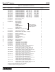
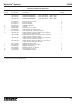
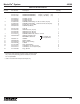
Table 2-2. Grease Reservoir Parts List - Continued
Item
Number Part Number Description Quantity
20 439-060-181 GASKET, Top Vent (3 lb.) 1
21 BUSHING, Follower 1
22 WASHER, Follower 1
23 WASHER, Support 1
24 NUT, Jam, 3/4-16 1
25 O-RING 1
26 RING, Retaining 1
27 527-000-230 PLUG, Low Level (3 lb.) 1
28 527-000-240 GASKET (3 lb.) 1
NOTE:
USED ON METAL
RESERVOIRS ONLY
FOR
OPTION
GP5
ONLY
3
4
5
22
7
23
26
21
25
24
20
2
3
4
5
6
7
8
B
16
17
1
18
A
9
10
11
28
27
13
12
15
*
14
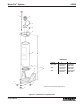
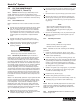
DIMENSIONS
OPTION A B
GP1, GM1, 7.25 inches 15 inches
GP2, GM2 (184 mm) (381 mm)
GP3, GM3 7.25 inches 22 inches
(184 mm) (559 mm)
GP4, GM4 7.25 inches 10.5 inches
(184 mm) (267 mm)
GP5 7.25 inches 6.87 inches
(184 mm) (174 mm)
19+
Figure 2-1. Grease Reservoir - Exploded View
Do not attempt to remove retain-
ing ring (2) or cable assembly (5),
(Figure 2-1) (or retaining ring (26)
or guide rod (5) for Option GP5).
Injury could result from sudden
expansion of spring (4).
WARNING
Items 21 through 26
are not serviceable
by the user; replace
entire reservoir.
* Mating fill coupler 506-322-000 (order separately)
+ Reservoir Tube Kit includes gasket (item 9).