
User's Manual


LTL-400Thrif-T Luber Low-Pressure Orifi ce Lubrication System
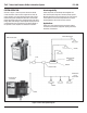
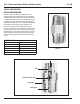
OPERATION
The electric gearmotor drives an eccentric (A) which reciprocates the
piston (B) in the pump body (C). The lubricant is discharged past an
internal check valve through the outlet (D). If lube system pressure
exceeds 10 bar(150 psi), the relief vale (E) automatically opens.
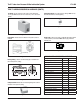
INSTALLATION
Connecting the pump for Remote Control using the machine
"PC" or some other external control - Input power may be brought
into the pump through either of the conduit holes on the left side of
the motor compartment. Subsequent electrical connection directions
are provided above. When these connections are made, the pump
motor's "On time" or output will be determined by the machine or
external system control.
For 60 Hz service, pump output will be 6.9 cm
3 (
.420 in.
3
) per
minute; on 50 Hz, it will be 5.7 cm
3
) (.350 in.
3
) per minute. For most
applications, we recommend that the pump operate a minimum of
one stroke (fi ve seconds "On") per lubrication cycle. When in doubt,
consult the factory.
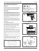
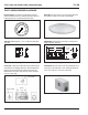
Connecting the pump for Time Control -
Set the slide switch to either minutes or hours for cycle time. Next,
set the desired pump "On time" using a screwdriver in the slotted
head of the scale marked "On time minutes". Then in a similar
fashion, set the specifi c interval at which lube cycles are to occur
using the appropriate scale under "total cycle time".
To fi nd "On time" in minutes = Total Output Required Per Cycle Time
(cu.in.) divided by .42 (60 Hz) or .35 (50 Hz).
When power is applied, the timer activates the lube pump motor and
simultaneously begins timing of the "On time" and "Total cycle time".
When the "On time" is completed, the timer shuts off the pump motor
but continues timing the "total cycle time" until the next cycle and
"On time".
Activation of the manual run button resets the cycle time to zero and
starts a lube cycle.
Input power may be brought in to the terminal strip through either of
two conduit holes on the left side of the compartment. Subsequent
electrical connection directions are provided above.
For more details, contact your Thrif-T Luber System distributor or the
factory.
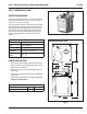
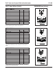
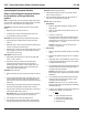
TIME CONTROL WIRING
TIME CONTROL WIRING
LOW LEVEL
L2
L1
7 8 9 10 11 12
123 456
MANUAL
RUN
INPUT
115
LOAD
3AMPS
MAN
RUN
NOT
USED
FAULT
M
AG
R
Figure 6
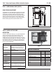
REMOTE
CONTROL
WIRING
1234
M
AG
R
MANUAL
RUN
LOW
LEVEL
FAULT
L1
L2
REMOTE
USER
CONTROL
Figure 7
Figure 8
Figure 9
THRIF-T LUBER ELECTRIC PUMP (CONT'D)
Page 5
Figure 10
1
2
5
7
10
13
ON TIME
MINUTES
02
4
8
16
24
32
30
5
24
16
8
5
4
2
TOTAL CYCLE TIME
MINUTES
HOURS
MINUTES HOURS
2