
User's Manual


Trabon
®
MGO
™
Series-Flo
®
Dividers
Page 2
L10141
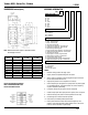
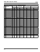
DIMENSIONS Inches/(mm) ORDERING INFORMATION
Note: Millimeter dimensions appear in parentheses below
decimal figure in inches.
Divider Assembly Sketch Example
MGO-4-450TCR-300S-600T-150C
Divider Valve With Indicator
Divider
Valve A—DIM. B—DIM. C—DIM.
MGO - 3 10.04 (255.1) 11.00 (279.4) 8.58 (217.8)
MGO - 4 11.78 (299.1) 12.75 (323.8) 10.31 (261.9)
MGO - 5 13.51 (343.2) 14.50 (368.3) 12.05 (305.9)
MGO - 6 15.25 (387.3) 16.25 (412.7) 13.78 (350.4)
MGO - 7 16.98 (431.2) 18.00 (467.2) 15.51 (394.0)
MGO - 8 18.71 (467.8) 19.75 (501.6) 17.25 (438.0)
MGO - 9 20.45 (519.3) 21.50 (546.1) 18.98 (482.1)
MGO - 10 22.18 (563.4) 23.25 (590.5) 20.72 (526.1)
MGO - 11 23.91 (607.3) 25.00 (635.0) 22.4 (570.2)
MGO – XX – XXX – X – XX
NUMBER OF SECTIONS
03 – Three
04 – Four
05 – Five
06 – Six
07 – Seven
08 – Eight
09 – Nine
10 – Ten
11 – Eleven
SECTION CAPACITY
150 – 0.150 cu.in.
300 – 0.300 cu.in.
450 – 0.450 cu.in.
600 – 0.600 cu.in.
TYPE OF SECTION
T – Twin
S – Single - Right Hand Outlet
L – Single - Left Hand Outlet
B – Twin w/Cycle Pin Right Side
C – Single w/Cycle Pin Right Side - Right Hand Outlet
D – Single w/Cycle Pin Right Side - Left Hand Outlet
E – Twin w/Proximity Switch Right Side
F – Single w/Proximity Switch Right Side - Right Hand Outlet
G – Single w/Proximity Switch Right Side - Left Hand Outlet
H – Twin w/Cycle Pin Left Side
J – Single w/Cycle Pin Left Side - Right Hand Outlet
K – Single w/Cycle Pin Left Side - Left Hand Outlet
M – Twin w/Proximity Switch Left Side
N – Single w/Proximity Switch Left Side - Right Hand Side
P – Single w/Proximity Switch Left Side - Left Hand Side
*CROSSPORTING OPTION
CR – Right Hand Side
CL – Left Hand Side
CB – Both Sides
*Omit when not required
NOTES:
Maximum working pressures: See page 1 Specs1.
Capacity sections are specified starting from inlet section2.
When a section is crossported, its outlet is plugged and output is diverted to 3.
the next section, farthest from the inlet
Single capacity sections can be crossported on one side only4.
Internal crossporting can be supplied on a capacity sec tion only when supplied 5.
on a manifolded assembly. If supplied as a loose unit, internal crossporting
may be accomplished by field drilling
Last section, farthest from inlet section, cannot be crossported6.
Indicate crossport option after capacity section if required, omit if not required7.
Preferred mounting is with pistons in horizontal position with inlet at top8.
Use discharge check valves for intermittent operation9.
Contact factory for availability of NPSF ported dividers10.
Divider systems should be limited to first and second stages only. Third 11.
staging is not recommended. Refer to Trabon bulletins L20101, L20105 and
L20115 for further in formation on system design