
User's Manual
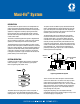


Trabon
®
Maxi-Flo
®
System
L23110
Page 5
DESIGN PROBLEM (Continued)
Maxi-Flo Pump Settings —
(For units having 115 V 60 Hz service only)
Time Control —
The time control unit Part No. 563379 (521-500-910) was selected
to supply the example system, therefore set the Solid State Timer
for "on" time required. See Lit. No. L13110.
Note: In systems where central pressure signaling is required
the pump should not be set for less than .120 cubic inches per
hour.
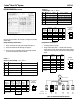
Stroke Control —
If stroke control unit Part No. – (521-500-420) is selected to supply
system, first determine electrical connections to machine cycle
control. Second, determine the average machine cycles per min.
(SPM). Third, determine the system design volume per hr. (Dv).
Fourth, using the following formula, calculate the pump stroke
setting (Ssc).
Should the calculated stroke setting fall between stroke increments
of the pump counter, it is necessary to calculate the actual output
delivered at both the higher and lower stroke settings and choose
the appropriate setting. Use the following formula to determine the
outputs at both settings.
Example:
A machine requires 2.77 cu.in. of lubricant per hr. to satisfy the
lube system. The machine averages 30 strokes per min. when in
operation. To determine the proper stroke setting, use Formula #1,
as above and proceed as follows:
The calculated stroke setting of 24 is between the 16 and 32
settings on the stroke counter. Therefore, outputs at the 16 and 32
stroke settings must be calculated to determine which setting would
be more appropriate to use. Outputs can be determined by using
Formula #2, as follows:
The lube system requirement was 2.77 Cu.In./Hr. If the 32 stroke
setting were selected (2.298 Cu.In./Hr.), the system would receive
17% less lubrication than required. If the 16 stroke setting was
selected (3.484 Cu.In./Hr.). the system would receive 26% more
lubrication than required. A decision can now be made s to
which stroke setting would be more appropriate for the particular
application.
Note:
The pump volume can be increased by lowering stroke settings
and decreased by increasing stroke setting.
Formula #1 (*0.06) x (SPM) x (B)
Ssc = Dv
Where: Ssc =
Calculated stroke setting for
pump counter
SPM =
Average machine strokes per
minute
Dv =
System design volume, cubic
inches per hour
A = *8.33 x Dv
B = *60 - A
*Constants
(0.06) x (SPM) x (B)
Dv
Solve for B A = 8.33 x Dv
= 8.33 x 2.77
= 23.07
B = 60 - A
= 60 - 23.07
= 36.93
(0.06) x (30) x (36.93)
Ssc = 2.77
Ssc =
24 Required stroke setting to
satisfy system requirements
Formula #1 (*3.6) x (SPM)
Output (cu.in) = Ssa + C
Where: Output =
Actual pump output, cubic
inches per hour
SPM =
Average machine strokes per
minute
Ssa =
Actual stroke setting for pump
counter
C = (*0.5) x (SPM)
*Constants
Output (cu.in.) =
3.6 x SPM
Ssa + C
Solve for C C = 0.5 x SPM
= 0.5 x 30
= 15
32 Stroke Setting
Output (cu.in.) =
3.6 x 30
32 + 15
Output (cu.in.) =
180
47
Output =
2.298 cu.in./hr @ 32 strokes
setting
16 Stroke Setting
Output (cu.in.) =
3.6 x 30
16 + 15
Output (cu.in.) =
180
31
Output = 3.484 cu.in./hr @ 16 stroke setting