
User's Manual


Trabon
®
Maxi-Flo
®
System
L23110
Page 4
!"#$%"&'
()*+,-
,.%/"0
!&12!(3!%4
5*+67
"*869
5*+67
"*869
:;
! "#$% $%! #
" "!!% !%" $!
& '$"% $%( $"
( $$!% )%! $!
# "#$% $%! #
* ($!% $%" $!
+,-./012345
%678%+9%:;/<:14=
>"?/34@//A
'"*%
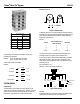
DESIGN PROBLEM (Continued)
Design Master Divider Valve —
List design volume for groups1.
Design master divider valve — consider each secondary 2.
divider valve as a point, with the total design volume required
equal to the total of all points served by the secondary divider
valves.
Note: Do not third state Maxi-Flo systems
Brg. Dia
.2
x Rows = Area A x T* = Vol./Hr
A (4) X 1 = 16 In
2
16 X .001 = .016 Cu. In./Hr.
B (4) x 1 = 16 In
2
16 x .001 = .016 Cu. In./Hr.
C (3) x 1 = 9 In
2
9 x .001 = .009 Cu. In./Hr.
D (3) x 1 = 9 In
2
9 x .001 = .009 Cu. In./Hr.
*T = .001 cubic inches/hour oil film replacement rate.
!"#$%&'
"(#)%"!#*&+
,&)%-./-%0
!"#$%&'
12&3
1$451"61.0
"!#*&+
&7.-(8
1$451"61.0
9:;&)(<&&=
/#*%'
(#)%3
/#*%'
(#)%3
>?
! "#$% "#$% "%# $%&
' "#$% "#$% "%# $%&
( )$$% $#$% # *
+ )$$% $#$% # *
,-./0+12345
%678%,9%:(0;:14< =*$%
5T
A
C
D
“MJ” Divider
Valve
Assembly
5S
B
5S
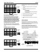
Brg. Dia. x L x = Area A x T* = Vol./Hr
E 3 X 4 X 3.14 = 38.0 In. 38.0 x .001 = .038 Cu. In./Hr.
F 3 x 4 x 3.14 = 38.0 In. 38.0 x .001 = .038 Cu. In./Hr.
G 2 x 2.5 x 3.14 = 16.0 In. 16.0 x .001 = .016 Cu. In./Hr.
H 1 x 2 x 3.14 = 6.0 In. 6.0 x .001 = .006 Cu. In./Hr.
I 1 x 2 x 3.14 = 6.0 In. 6.0 x .001 = .006 Cu. In./Hr.
*T = .001 cubic inches/hour oil film replacement rate.
!"#$%&'
"(#)%"!#*&+
,&)%-./-%0
!"#$%&'
12&3
1$451"61.0
"!#*&+
&7.-(8
1$451"61.0
9:;&)(<&&=
/#*%'
(#)%3
/#*%'
(#)%3
>?
! "#$% "#$% "%# &'
( "#$ "#$% "%# &'
) *'$% *'$% *%' "
+ *$$% $'$% ' ,
- *$$% $'$% ' ,
./012345678
%9+:%.-%;<2=;47> ?''%
5T
10S
H
I
E
10S
F
G
5S
“MJ” Divider
Valve
Assembly
5T
10S
5
1
6
5S
3
4
10T
Master
“MJ” Divider
2
Pump
5T
10T
10S
5S
5S
5S
5T
15S
5T
5S
15T
10S
10S
5S
5S
Group #1
#2
#3 #6 #4 #5
.052
.100.104
.208
.112
.052
Cu. in./hr.
.63 cu. in./hr.
5T
10S
5S
10S
15S
15T
5T
5S
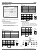
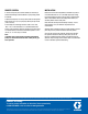
Figure 7 Machine Bearing List
Given the above information, the next step is to design the secondary
divider valves.
Design Secondary Divider Valves —
Group 1 illustrates four single roller bearings (See Figure 7).1.
Group 2 illustrates five plain bearings (See Figure 7).2.
Group 3 thru 6 are not detailed; however total design volumes 3.
(cu.in./hr.) and MJ divider valves are shown.
Group 1 —
Single row roller bearings — Vol = D
2
R x T*
Group 2 —
Plain Bearings — Vol = π DL x T*