
User's Manual
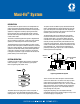


Trabon
®
Maxi-Flo
®
System
L23110
Page 3
Note: In systems where central pressure signaling is
desired the following is recommended:
If the oil to be used in the system is less than 2000 SUS
(actual), substitute .010 cubic inches per hour (design
volume) for all bearings where the calculated volume is less
than .010 cubic inches per hour. If using oil above 2000
SUS (actual), substitute .005 cubic inches per hour (design
volume) for all bearings where the calculated volume is less
than .005 cubic inches per hour. Oils with viscosities less
than 300 SUS (actual) are not recommended.
When a whole number cannot be obtained, use the next higher
whole number. In this case the 18.5 ratio requirement will be a
10 S size intermediate section, thus providing .020 cubic inches
per cycle.
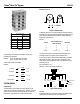
DESIGNING A MAXI-FLO SYSTEM
The design procedure for a Maxi-Flo centralized lubrication system
is as follows:
Survey machine (See Figure 6 machine survey) and group 1.
bearings
Determine type of Maxi-Flo pump best suited for the 2.
application
Time Controlled •
Stroke Controlled •
Remote Controlled (Refer to Graco Product Specs •
and Ordering Lit.)
Calculate bearing requirements (Refer to Lit No. L20115)3.
Design secondary divider valve assemblies4.
Design master divider valve assembly5.
Determine total system oil requirement in cubic inches per 6.
hour
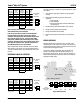
DESIGN PROBLEM
MJ Divider Valves are to be used with a .001 cu.in/hour oil film
replacement rate. A SAE 30wt oil is to be used in the system, and
a central pressure signal is desired. The Maxi-Flo time control unit
has been selected to supply the system.
The machine contains 25 lubrication points which have been
grouped. Lube volumes have been assigned to groups 3—6.
(See Figure 6 machine survey). Groups 1 and 2 are contained on
machine bearing list Figure 6, and will be used as the example for
designing the divider valves.
Figure 6 Machine Survey
!"#$%&'
"(#)%"!#*&+
,&)%-./-%0
!"#$%&'
12&3
1$451"61.0
"!#*&+
&7.-(8
1$451"61.0
9:;&)(<&&=
/#*%'
(#)%3
/#*%'
(#)%3
>?
! "##$ #%#$ #$% &
' &##$ #%#$ #$% &
( #)#$ #)#$ #$) #"
* #"#$ #"#$ #$" #%
+ #"#$ #"#$ #$" #%
, "##$ #%#$ #$% &
- #%#$ #%#$ #$% &
./012*34567
$89:$.;$<(2=<36> #"%$
5T
10T
A
B
F
D
10S
C
G
E
5T
“MJ” Divider
Valve
Assembly
!"#$%&'
"(#)%"!#*&+
,&)%-./-%0
!"#$%&'
12&3
1$451"61.0
"!#*&+
&7.-(8
1$451"61.0
9:;&)(<&&=
/#*%'
(#)%3
/#*%'
(#)%3
>?
! ""#$ ""#$ % "#
& '(#$ '(#$ )$* '$(+
, "'"$ "'"$ # '
- "'"$ "'"$ # '
. ""#$ ""#$ % "#
/0123-45678
$9:;$/<$=,3>=47? "%#$
5T
A
E
B
C
D
“MJ” Divider
Valve
Assembly
10T
10S
!"#$%&'
"(#)%"!#*&+
,&)%-./-%0
!"#$%&'
12&3
1$451"61.0
"!#*&+
&7.-(8
1$451"61.0
9:;&)(<&&=
/#*%'
(#)%3
/#*%'
(#)%3
>?
! "#"$ "#"$ % &
' "%"$ "%"$ # "(
) "*"$ "*"$ + &(
, "#"$ "#"$ ( &
-./01,23456
$789$-:$;)1<;25= "%($
15S
A
D
B
C
“MJ” Divider
Valve
Assembly
10T
10S
A
B
C
D
JK
LM
N
P
O
Q
R
S
T
U
VW
X
Y
Typical Machine
5S
5T
10S
15S
5T
5S
15T 5S
15S
10S
5S
15T
5S
5T
10S
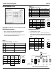
1
.052
2
.112
3
.206
4
.100
5
.052
6
.104
Letter-Bearing Location
5T
5S
10S
5S
Group
Design Volume
Cu.In./Hr.
A
B
C
D
JK
LM
N
P
O
Q
R
S
T
U
VW
X
Y
Typical Machine
5S
5T
10S
15S
5T
5S
15T 5S
15S
10S
5S
15T
5S
5T
10S
1
.052
2
.112
3
.206
4
.100
5
.052
6
.104
Letter-Bearing Location
5T
5S
10S
5S
Group
Design Volume
Cu.In./Hr.