
User's Manual

L51010
Manzel
®
Model 25 Lubricator
™
Page 5
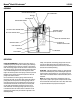
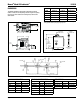
DIMENSIONS
To establish installation requirements, determine the desired
number of feeds, the corresponding reservoir length, the capacity,
the center-to-center distance of mounting holes, and the drive
shaft location.
461-000-150
7/8-18 THD.
7/8-18 THD.
7/8-18 THD.
5/8 HEX.
12
4
3
2
1
5
10
9
8
7
2
14
6
11
11
2
13
.32
(8.1)
6.50
(165.1)
8.50
(215.9)
6.00
(152.4)
1/4-18 NPSF
LUBE OUTLET
RESERVOIR
1/2 NPT
CONDUIT
CONNECTON
LEVEL OPTION
(L1&L2)
4.25
(107.9)
"B"
2.00
(50.8)
"A"
FULL
EMPTY
0.50
(12.8)
"B"
SEALED COMPT. OPTION
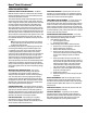
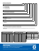
Description Part No. Old Part No.
(1) Bearing 560146 402-080-020
(2) Nut 560155 410-700-050
(3) Packing 556752 439-079-230
(4) Spacer 560229 424-050-180
(5) Spacer – 424-050-200
END BEARING
Description Part No. Old Part No.
(12) Bearing 560133 402-040-000
(13) Oil Seal 556575 423-010-180
(14) Bearing 560128 402-000-040
BEARING SUPPORT OPTION
Description Part No. Old Part No.
(6) Bearing 560142 402-060-000
(7) Bushing 560143 402-060-010
(8) Bearing 560144 402-060-070
(9) Screw 558647 415-020-020
(10) L’Washer 558685 421-060-080
(11) Spacer 560229 424-050-180
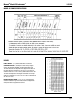
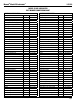
No. of
Feeds
Reservoir
Length (A)
C to C or End
Lugs (B)
Approx
Capacity Pints
1 - 4 7-9/32 in 8-27/32 in 6-1/4
5 - 8 11-19/32 in 12-27/32 in 9-1/4
9 - 12 16-19/32 in 17-27/32 in 13
13 - 16 20-19/32 in 21-27/32 in 16
17 - 20 25-19/32 in 26-27/32 in 19-3/4
Table makes dimensional allowance of 1 in for each Center Bearing,
evenly spaced between pumping unit groups of 8.