
User's Manual


ORDERING INFORMATION
All written and visual data contained in this document are based on the latest product information available at the time of publication. Graco reserves the right to make changes at any time without notice.
Contact us today!
To receive product information or talk with a Graco representative,
call 800-533-9655 or visit us online at www.graco.com.
©2006-20011 Graco Inc. Form No. L10103 Rev. D 01/12 Available online only All other brand names or marks are used for identification purposes and are trademarks of their respective owners. All written
and visual data contained in this document are based on the latest product information available at the time of publication. Graco reserves the right to make changes at any time without notice.
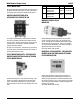
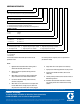
XXX – XXX – X – X – XX – X – XX
SERIES OF DIVIDERS
MHH - High Pressure Compressor to 7,500 psi (fluoroelastomer seals)
INLET - OUTLET THREADS
NPT - Inlet 1/4-18, Outlet 1/8-27
SAE - Inlet 7/16-20, Outlet 7/16-20
DIVIDER VALVE ACCESSORY OPTIONS (OMIT WHEN NOT REQUIRED)
P - Assembly of Performance Indicators (in all working outlets **)
C - Assembly of External Check Valves (in all working outlets **)
B - Assembly of Performance Indicators & Check Valves (in all working outlets **)
NUMBER OF SECTIONS
3 - Three 6 - Six
4 - Four 7 - Seven
5 - Five 8 - Eight
WORKING SECTION CAPACITY
06 - 0.006 cu. in. 18 - 0.018 cu. in. BP - Bypass
09 - 0.009 cu. in. 24 - 0.024 cu. in.
12 - 0.012 cu. in. 30 - 0.030 cu. in.
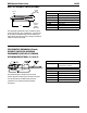
TYPE OF VALVE SECTION
T - Twin Valve S - Single Valve - RH Outlet L - Single Valve - LH Outlet
B - Twin Valve w/Cycle Pin Right C - Single Valve w/Cycle Pin Right - LH Outlet D - Single Valve w/Cycle Pin Right - RH Outlet
H - Twin w/Cycle Pin Left J - Single w/Cycle Pin Left - RH Outlet K - Single w/Cycle Pin Left- LH Outlet
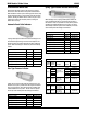
CROSS PORTING OPTION (OMIT WHEN NOT REQUIRED)
CR - Right Hand Side
CL - Left Hand Side
CB - Both Sides
**Performance Indicator/Check Valve part number must be
specified on order.
If a Proximity Switch is required, order as a separate item
(see bulletin L15600).
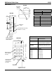
NOTES:
1. Right/left hand is determined when viewing front of
divider valve assembly with inlet at top.
2. Working sections are specified starting from inlet
section down.
3. When valve is cross ported, its outlet is plugged and
output is diverted to next valve farthest from inlet.
4. Last valve in divider assembly, farthest from inlet,
cannot be cross ported.
5. When valve is a twin, both outlets in its sub-plate must
be used. When valve is a single, only one outlet in its
sub-plate can be used and the other must be plugged.
6. Single valve can be cross ported on one side only.
7. Cycle pins are limited to applications of 3,500 psi max.
8. Cycle pins are available on MHH 18, 24 & 30 size
valves only.
9. Fsmech proximity switches can be used on all sizes of
MHH working sections.
10. All divider valve assemblies must have a minimum
of 3 working sections and a maximum of 8 working
sections.