
User's Manual


Setup
3A2797G 41
18.
IsoGuard Select Fluid System Setup
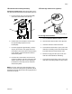
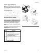
Component A (Red) Pump: Fill IsoGuard Select reser-
voir (LR) with IsoGuard Select fluid (provided by Graco).
a. Lift the reservoir (LR) out of the bracket (RB)
and remove the container from the cap.
b. Fill with fresh fluid. Thread the reservoir onto
the cap assembly and place it in the
bracket (RB).
c. Push the supply tube approximately 1/3 of the
way into the reservoir. The supply tube is the
tube with the check valve with an arrow pointing
in the direction of flow towards the IsoGuard
Select fluid cylinder.
d. Push the return tube into the reservoir until it
reaches the bottom. The return tube is the tube
with the check valve with an arrow pointing in
the direction of flow away from the IsoGuard
Select fluid cylinder.
NOTE: The return tube must reach the bottom of the
reservoir to ensure that isocyanate crystals will settle to
the bottom and not be siphoned into the supply tube and
returned to the pump.
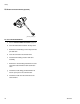
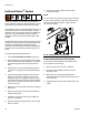
19.I
nstall High Volume Fill Kit (Optional).
a. Perform Pressure Relief Procedure, page 44.
b. Close the ball valves located on the day tanks.
c. Insert the refill valve onto the ball valve.
d. Connect the air tube from the “open” port on the
refill valve to the fitting on the solenoid valve that
is located inside the tank stand base cube.
e. Remove the plug from other port on the sole-
noid valve and install the air tube fitting.
f. Connect the air tube from the “close” port on the
refill valve to the fitting installed in step e above.
LR
RB
24C352_313998_8e
F
IG
. 23: High Volume Refill Kit
r_24m419_3a1961_1a