
User's Manual


Setup
40 3A2797G
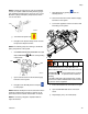
15.
Install GX-16 Orifices
a. Close both A side (Red) and B side (Blue) feed
inlet valves on the system. See F
IG
. 2 on page
14.
b. Close A side (Red) material return ball valves
on the material tank stand.
c. Follow Pressure Relief Procedure on page 44.
d. Remove plugs from GX-16.
e. Install orifices provided.
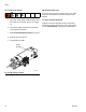
16.
Pressure check hose
See hose manual. Pressure check for leaks. If no leaks,
wrap hose and electrical connections to protect from
damage.
17.
Check hydraulic fluid level
Hydraulic reservoir is filled at the factory. Check fluid
level before operating the first time, and weekly thereaf-
ter. See Technical Data on page 95 for specifications.
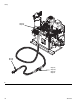
F
IG
. 22: GX-16 Plug Location
ti17747a
Orifice
(A) Side