
User's Manual


Setup
3A2797G 39
NOTE: A minimum feed pressure of 50 psi (0.35 MPa,
3.5 bar) is required at both feed inlet pressure gauges
(FP). Maximum feed pressure is 75 psi (
517 kPa, 5.2 bar)
.
Maintain A (Red) and B (Blue) feed pressures within
10% of each other.
g. Turn HFR main power ON .
h. Navigate to the System Setup Screen. Set the
low pressure dispense to 25%.
NOTE: The following steps are referring to the B side
(Blue) components of the system.
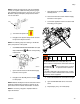
i. Set PRESSURE RELIEF/DISPENSE valve (SA,
SB) to DISPENSE for the corresponding
material side.
j. Open feed inlet valve and the material supply
ball valve on the system.
k. Navigate to the Standby Screen and push
to start pumps.
NOTE: Material will dispense into the container from the
applicator material hose at this time. Continue to dis-
pense fluid until no material contamination is noticed.
NOTE: If necessary, navigate to Operator Mode to
adjust the flowrate
l. Stop dispensing by pushing from the
Standby Screen.
m. Close feed inlet valve and the material supply
ball valve on the system.
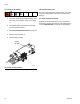
n. Connect the applicator return hose to the fluid
inlet fitting on the system.
o. Ensure all material hose connections are tight.
p. Open the RETURN ball valves on the tank
stand.
q. Repeat steps j thru p for A side (Red).
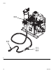
FP
ti10006a1
ti9877a1
SA
SB
F
IG
. 21: Return Lines
Do not install shutoffs downstream of the PRESSURE
RELIEF/DISPENSE valve outlets (BA, BB). The
valves function as overpressure relief valves when set
to DISPENSE . Lines must be open so valves
can automatically relieve pressure when machine is
operating.
If circulating fluid back to the supply drums, use high
pressure hose rated to withstand the maximum work-
ing pressure of this equipment.