
User's Manual


Setup
34 3A2797G
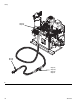
h. Connect cables (Y). Be sure cables have slack
when hose bends. Wrap cable and electrical
connections with electrical tape. See Heated
Hose manual for heated hose connection
details and illustrations for the various types of
heated hoses.
i. Connect the other end of the supply hoses
(solid color) to the applicator. See the applicator
manual for fluid inlet identification.
j. Connect A (Red) and B (Blue) return hoses
(solid with white stripe) to the applicator. See
the applicator manual for fluid outlet identifica-
tion.
NOTE: The other end of the return hose will be con-
nected in step n on page 39.
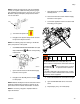
11.
Connect GX-16 Hydraulic Lines
a. Navigate to the System Screen 2 and set the
mode to run as straight head: prox dispense
valve.
b. Verify the mixhead hydraulic power pack is not
active by verifying the gauge is at 0.
c. Check the hydraulic fluid level. See Technical
Data on page 95 for specifications.
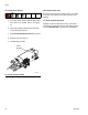
d. Use the supplied 7/16 in. JIC male-male
adapter at the gun end to connect hoses
Y
Trapped air can cause the pump to cycle unexpectedly,
which could result in serious injury from splashing or
moving parts.
F
IG
. 17: Gauge