
User's Manual

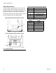


Setup
30 3A2797G
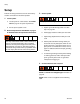
5.
Connect HFR Proximity Cables to the GX-16.
NOTE: Refer to the HFR and GX-16 manuals for more
details for the following procedures.
NOTE: The cable is indicated by a green stripe.
a. Connect the GX-16 proximity sensor to the
proximity cable.
b. Connect the 10 ft (3 m) hydraulic whip hose
cable to the 25 ft (7.6 m) chemical hose cable.
c. Connect the other end of the cable to the electri-
cal connector found near the fluid manifold on
the HFR.
NOTE: The electrical connector will be indicated by a
green stripe and labeled “PG-MPO”.
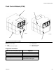
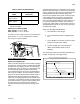
6.
Connect Hydraulic Lines to the system.
a. Connect the hydraulic hose to the hydraulic
hose fittings (A2 and B2) on the AC power pack.
b. Hand tighten each fitting.
c. Tighten each fitting 1/4 turn past hand tight.
NOTICE
Damage can occur to the directional valve if the
hydraulic hose diameter is larger than 3/8 in.
(9.5 mm).
To prevent damage to the applicator or directional
valves, do not allow any dirt or foreign matter to
enter the lines, when connecting the hose kit to the
applicator and hydraulic power pack.
Hydraulic
Hose Fitting
Hydraulic
Hoses
Hydraulic Hose
Color Markings
A2 Material close Green
B2 Material open Green/White
F
IG
. 14: Hydraulic Fittings on Hydraulic Housing
B2
A2
ti19515a