
User's Manual


Component Identification
3A2797G 25
Temperature Control Module Diagnostic
Information
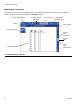
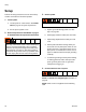
Module Status LEDs
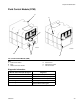
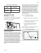
Heat Control Zone Selection
The HFR unit supports four independent temperature
control zones and two independent temperature moni-
toring zones. The high power temperature control mod-
ules are located inside the frame below the hydraulic
power pack.
Signal Description
Green on Temperature control module is
powered up.
Yellow on Internal communication in prog-
ress.
Red solid Temperature control module failure.
See Troubleshooting table.
Red flashing
fast
Uploading software.
Red flashing
slow
Token error. Remove token and
upload software token again.
Blue light off
(High Power
Module only)
Temperature control module is off.
See Troubleshooting table.
Blue flashing
(High Power
Module only)
Length of flashes indicates amount
of power running through tempera-
ture control module.
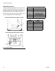
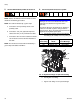
Primary Heater B (Blue)
Primary Heater A (Red)
Right Side from
Rear View
Left Side from
Rear View
ti17748a
ti17749a
Material Temperature
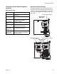
FTS - (Red)