
User's Manual


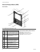

Component Identification
3A2797G 19
Diagnostic Information
7
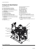
Ref Description
A Access Cover
B LEDs
C Warning Label
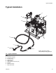
1A, 1B CAN Connections
2 Three-way Splitter to: Oil Low Level
Sensor, Dispense Valve Solenoid, and
Footswitch
3 Oil Temperature Sensor
5 Electric Motor Temperature Sensor
6 LVDT (Position Sensor)
7 Three-way Splitter to:
Hydraulic Directional Valve,
Oil Overtemperature Switch
8 Pressure Transducer B (Blue) side
9 Pressure Transducer A (Red) side
10 Not used
11 Motor Position Sensor
12 MCM Power Input Connection
13 Motor Power Connection
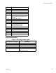
Table 1: LED (Ref B) Status Signal
Module Status LED Signal Description
Green on System is powered up.
Yellow on Internal communication in progress.
Red solid MCM hardware failure. Replace MCM.
Red flashing fast Uploading software.
Red flashing slow Token error. Remove token and upload
software token again.