
User's Manual
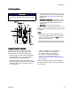
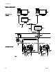

Installation
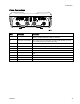
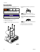
Key
A1 and A2
Flow Meter
Supplied in some kits. See
Parts, page 34.
B1 and B2 ProControl 1K
EModulewithBracket
Supplied
C Power Supply a
nd Barrier
SuppliedinHa
zardous Location
Kits
D1 and D2 Meter Cable (50 ft., 15 m) Supplied in kits with meter
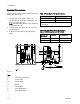
E
Power Cord (10 ft., 3 m), not shown Supplied in Non-Hazardous
Location Kits
F
Power Cable (50 ft., 15 m) Supplied
G Fiber Optic Cable (100 ft., 30 m)
Accessory
H
Serial Cable
Accessory
J
Advanced Web Interface
Accessory
K
Ethernet Cable
Accessory
L Personal computer Not supplied.
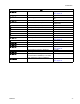
N1 and N2
Fluid Regulator
Supplied in some kits. See
Parts, page 34.
P
Air Cont
rol Module
Accessory
Q1 and Q2
Air Lines Not supplied
R1 and R2 Flow Con
trol Cable
Supplie
d
S1 and S
2
Pressure Transducer
Suppli
ed in some kits. See
Parts,
page 34.
T1 and T2 I/P Transducer (Current to Pressure) Supplied
U1 and U2
Mounti
ng Panel
Supplied
V1 and V2 Splitter to meter and light tower
(non-hazardous installations) or IS cable
kit for hazardous location installations.
Acces
sory
W1 and W2 Pressure Transducer Cable. Supplied in some kits. See
Parts, page 34.
3A2614F
17