
User's Manual

Installation
Air Connectio
ns
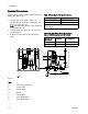
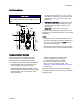
NOTICE
To avoid damage to the I/P transducer, use clean,
dry, oil-free air, filtered through at least a 40 micron
filter.
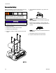
1. Connect incom
ing air line (Q) to 1/4 in. npt (f)
inlet (AB) on
I/P transducer (T). Kits with a fluid
regulator (S
ee Parts, page 34), include a 3/8
tube fitting.
2. Kits with flu
id regulator: Check that the air tube
is connecte
dfrom5/32tubefitting(AC)onI/P
transducer
to 5/32 tube fitting (AD) on fluid
regulator (
N).
Other Kits:
The air outlet is 1/4 in npt (f).
The I/P transducer exhausts a small amount of air
whenever air is connected, whether or not the system
is operating.
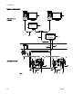
NOTE:
•Thetoppo
rt (AH) on the fluid regulator can be
used for h
igh-speed flushing with an independent
air sourc
e. Set the air pressure higher than the
side por
t (AD) air pressure.
• Flushin
g air pressure must be removed from the
top port
(AH) to return to the previous flow setting.
Commun
ication Options
Graco Accessories are available to enable
communication with a Programmable Logic
Controller (PLC) or Personal Computer (PC).
• The Fiber Optic Converter (Graco Kit 24N978)
enables Modbus RTU communication with a
user-supplied PLC using a serial cable.
• A Modbus Gateway (Graco Kit 24N977) used
with a Fiber Optic Converter (Graco Kit 24N978)
enables Modbus TCP communication with a
user-suppled PLC.
• A Modbus Gateway (Graco Kit 24N977)
canbeconnectedto(orinstalledin)
an Advanced Web Interface (Graco
Kit 15V377) to enable communication
with a PC using an ethernet cable. See
Appendix B - Advanced Web Interface, page 48,
for instructions.
These communication kits come with installation
and setup directions necessary for their use with the
ProControl 1KE.
3A2614F 15