
User's Manual

Installation
Electrical Co
nnections
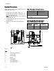
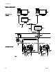
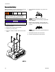
Install per Graco Control Drawing 16M169, in Manual
332013. See also Figure 1.
1. Connect main
power supply cord (E, not
supplied) th
rough strain relief to terminals L and
N on the power
supply unit.
Note: Use ei
ther strain relief (5) or (6), depending
onthesizeo
fthecord.
2. Connect pow
er cord ground wire (W) to ground
terminal bl
ock (Y).
3. Connect IS
power cable (F) per the following
table.
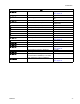
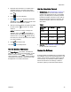
Table 1 Power Barrier Wiring Connections
Power Cable Le
ads
Barrier Conne
ction
Brown (power) Connector 1
Blue (common) Connector 2
Glossy Blac
k (ground) and Black (drain) connect to
ground blo
ck.
Table 2 I/
P Transducer Wiring Connections;
Cables 16P790 (non-IS) and 16V142 (IS)
Wiring Table
Wire Color
Function
DIN Conne
ctor
Gray Control A Connector 1
Blue
Common Connect
or 2
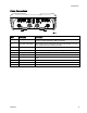
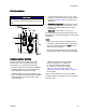
Figure 1
KEY
E
Inbound AC Power Cord
F
P
ower Cable
W
Ground Wires
XBarrier
Y
Ground Block
5
Strain Relief Fitting
6
Strain Relief Fitting
1
4
3A2614F