
User's Manual


Rear Wheel and Wheel Motors
3A2593B Repair 37
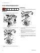
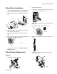
Wheel Motor Installation
1. Connect two hydraulic hoses (112) to wheel motor
(21a) and insert wheel motor (21a) into frame (1).
2. Install distance sensor (4) and clamp (5) with screw
(6).
3. Install wheel motor (21a) and fender (19) with four
bolts (78) and lock nuts (79).
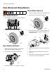
4. Install wheel hub (22b), castle nut (21b), and pin
(56).
5. Install wheel (16) and four lug nuts (22). Alternately
tighten lug nuts opposite each other.
6. Purge hydraulic system. See Hydraulic System
Purging, page 12.
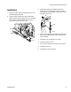
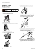
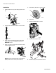
Wheel Sensor Replacement
Removal
1. Remove tank lid and siphon tube.
2. Remove tank from unit.
3. Use wrench to remove six screws from front shield
and remove front shield from unit.
4. Place jack under frame near pump-side wheel and
raise jack.
5. Remove four lug nuts (22) and wheel (16).
6. Disconnect wheel sensor connector from wire har-
ness.
7. Use wrench to remove screw (6), clamp (5), and
wheel sensor (4).
22b
78
21a
79
112
21b
ti18584a
56
19
6
5
4
ti18589a
22
16
ti24916a
ti19163a
ti18589a
22
16
ti19328a
ti19099a
4
5
6